The magnetic field (see § 109) has an orienting effect on the current-carrying frame. Consequently, the torque experienced by the frame is the result of the action of forces on its individual elements. Summarizing the results of a study of the effect of a magnetic field on various current-carrying conductors, Ampere established that the force d F, with which the magnetic field acts on the conductor element d l with current in a magnetic field is directly proportional to the current strength I in the conductor and the cross product of an element of length d l conductor for magnetic induction B:
d F = I. (111.1)
Direction of vector d F can be found, according to (111.1), using the general rules of vector product, which implies left hand rule: if the palm of the left hand is positioned so that vector B enters it, and the four extended fingers are positioned in the direction of the current in the conductor, then the bent thumb will show the direction of the force acting on the current.
Ampere force modulus (see (111.1)) is calculated by the formula
dF = I.B. d l sin, (111.2)
where a is the angle between vectors dl and B.
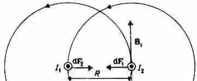
Ampere's law is used to determine the strength of interaction between two currents. Consider two infinite rectilinear parallel currents I 1 And I 2 (current directions are indicated in Fig. 167), the distance between which is R. Each of the conductors creates a magnetic field, which acts according to Ampere's law on the other conductor with current. Let's consider the strength with which the magnetic field of the current acts I 1 per element d l second conductor with current I 2. Current I 1 creates a magnetic field around itself, the lines of magnetic induction of which are concentric circles. Vector direction b 1 is given by the rule of the right screw, its module according to formula (110.5) is equal to
Direction of force d F 1, from which the field B 1 acts on section d l the second current is determined by the left-hand rule and is indicated in the figure. The force module, according to (111.2), taking into account the fact that the angle between the current elements I 2 and vector B 1 straight line, equal 
d F 1 =I 2 B 1 d l, or, substituting the value for IN 1 , we get

Using similar reasoning, it can be shown that the force d F 2, with which the magnetic field of the current I 2 acts on element d l first conductor with current I 1 , is directed in the opposite direction and is equal in magnitude

Comparison of expressions (111.3) and (111.4) shows that
i.e. two parallel currents of the same direction attract each other with force

If currents have opposite directions, then, using the left-hand rule, we can show that between them there is repulsive force, defined by formula (111.5).
45.Faraday's law and its derivation from the law of conservation of energy
Summarizing the results of his numerous experiments, Faraday came to the quantitative law of electromagnetic induction. He showed that whenever there is a change in the magnetic induction flux coupled to the circuit, an induced current arises in the circuit; the occurrence of an induction current indicates the presence of an electromotive force in the circuit, called electromotive force of electromagnetic induction. The value of the induction current, and therefore e. d.s, electromagnetic induction ξ i are determined only by the rate of change of magnetic flux, i.e.

Now we need to find out the sign of ξ i . In § 120 it was shown that the sign of the magnetic flux depends on the choice of the positive normal to the contour. In turn, the positive direction of the normal is related to the current by the rule of the right screw (see § 109). Consequently, by choosing a certain positive direction of the normal, we determine both the sign of the magnetic induction flux and the direction of the current and emf. in the circuit. Using these ideas and conclusions, we can accordingly arrive at the formulation Faraday's law of electromagnetic induction: whatever the reason for the change in the flux of magnetic induction, covered by a closed conducting circuit, arising in the emf circuit.

The minus sign shows that an increase in flow (dФ/dt>0) causes emf.
ξξ i<0, т. е. поле индукционного тока направлено навстречу потоку; уменьшение
flow (dФ/dt<0) вызывает ξ i >0,
i.e., the directions of flow and induced current fields coincide. The minus sign in formula (123.2) is a mathematical expression of Lenz's rule - a general rule for finding the direction of induction current, derived in 1833.
Lenz's rule: the induced current in the circuit always has such a direction that the magnetic field it creates prevents the change in the magnetic flux that caused this induced current.
Faraday's law (see (123.2)) can be directly derived from the law of conservation of energy, as was first done by G. Helmholtz. Consider a conductor carrying current I, which is placed in a uniform magnetic field perpendicular to the plane of the circuit and can move freely (see Fig. 177). Under the influence of Ampere force F, the direction of which is shown in the figure, the conductor moves to a segment dx. Thus, the Ampere force produces work (see (121.1)) d A=I dФ, where dФ is the magnetic flux crossed by the conductor.
If the loop impedance is equal to R, then, according to the law of conservation of energy, the work of the current source during the time dt (ξIdt) will consist of work on Joule heat (I 2 Rdt) and work on moving a conductor in a magnetic field ( I dФ):
![]()

where-dФ/dt=ξ i is nothing more than Faraday's law (see (123.2)).
Faraday's law can also be formulated this way: emf. ξ i electromagnetic induction in a circuit is numerically equal and opposite in sign to the rate of change of magnetic flux through the surface bounded by this circuit. This law is universal: e.m.f. ξ i does not depend on the way the magnetic flux changes.
E.m.f. Electromagnetic induction is expressed in volts. Indeed, given that the unit of magnetic flux is weber(Wb), we get

What is the nature of emf. electromagnetic induction? If the conductor (the movable jumper of the circuit in Fig. 177) moves in a constant magnetic field, then the Lorentz force acting on the charges inside the conductor, moving along with the conductor, will be directed opposite to the current, i.e. it will create an induced current in the conductor in the opposite direction (the direction of the electric current is taken to be the movement of positive charges). Thus, the excitation of the emf. induction when the circuit moves in a constant magnetic field is explained by the action of the Lorentz force that arises when the conductor moves.
According to Faraday's law, the occurrence of emf. electromagnetic induction is also possible in the case of a stationary circuit located in variable magnetic field. However, the Lorentz force does not act on stationary charges, so in this case it cannot explain the occurrence of emf. induction. Maxwell to explain the emf. induction in stationary conductors suggested that any alternating magnetic field excites an electric field in the surrounding space, which is the cause of the appearance of induced current in the conductor. Vector circulation E IN this field along any fixed contour L conductor represents the emf. electromagnetic induction:

47.. Loop inductance. Self-induction
An electric current flowing in a closed circuit creates a magnetic field around itself, the induction of which, according to the Biot-Savart-Laplace law (see (110.2)), is proportional to the current. The magnetic flux Ф coupled to the circuit is therefore proportional to the current I in the outline:
Ф=LI, (126.1)
where is the proportionality coefficient L called circuit inductance.
When the current in the circuit changes, the magnetic flux associated with it will also change; therefore, an emf will be induced in the circuit. Emergence of e.m.f. induction in a conducting circuit when the current strength changes in it is called self-induction.
From expression (126.1) the unit of inductance is determined Henry(H): 1 H - the inductance of such a circuit, the self-induction magnetic flux of which at a current of 1 A is equal to 1 Wb:
1 Gn=1 Vb/A=1V s/A.
Let's calculate the inductance of an infinitely long solenoid. According to (120.4), the total magnetic flux through the solenoid
(flux linkage) is equal to 0( N 2 I/ l)S. Substituting this expression into formula (126.1), we obtain

i.e. the inductance of the solenoid depends on the number of turns of the solenoid N, its length l, area S and magnetic permeability of the substance from which the solenoid core is made.
It can be shown that the inductance of a circuit in the general case depends only on the geometric shape of the circuit, its size and the magnetic permeability of the environment in which it is located. In this sense, the inductance of the circuit is an analogue of the electrical capacitance of a solitary conductor, which also depends only on the shape of the conductor, its dimensions and the dielectric constant of the medium (see §93).
Applying Faraday's law to the phenomenon of self-induction (see (123.2)), we obtain that the emf. self-induction

If the circuit is not deformed and the magnetic permeability of the medium does not change (later it will be shown that the last condition is not always satisfied), then L=const and

where the minus sign, due to Lenz's rule, shows that the presence of inductance in the circuit leads to slowing down change current in it.
If the current increases over time, then
dI/dt>0 and ξ s<0, т. е. ток самоиндукции
is directed towards the current caused by an external source and inhibits its increase. If the current decreases over time, then dI/dt<0 и ξ s > 0, i.e. induction
the current has the same direction as the decreasing current in the circuit and slows down its decrease. Thus, the circuit, having a certain inductance, acquires electrical inertia, which consists in the fact that any change in current is inhibited the more strongly, the greater the inductance of the circuit.
59.Maxwell's equations for the electromagnetic field
Maxwell's introduction of the concept of displacement current led him to the completion of his unified macroscopic theory of the electromagnetic field, which made it possible from a unified point of view not only to explain electrical and magnetic phenomena, but also to predict new ones, the existence of which was subsequently confirmed.
Maxwell's theory is based on the four equations discussed above:
1. The electric field (see § 137) can be either potential ( e q), and vortex ( E B), therefore the total field strength E=E Q+ E B. Since the circulation of the vector e q is equal to zero (see (137.3)), and the circulation of the vector E B is determined by expression (137.2), then the circulation of the total field strength vector

This equation shows that the sources of the electric field can be not only electric charges, but also time-varying magnetic fields.
2. Generalized vector circulation theorem N(see (138.4)):

This equation shows that magnetic fields can be excited either by moving charges (electric currents) or by alternating electric fields.
3. Gauss's theorem for the field D:

If the charge is distributed continuously inside a closed surface with volume density , then formula (139.1) will be written in the form

4. Gauss’s theorem for field B (see (120.3)):

So, the complete system of Maxwell's equations in integral form:
The quantities included in Maxwell’s equations are not independent and the following relationship exists between them (isotropic non-ferroelectric and non-ferromagnetic media):
D= 0 E,
B= 0 N,
j=E,
where 0 and 0 are the electric and magnetic constants, respectively, and - dielectric and magnetic permeability, respectively, - specific conductivity of the substance.
From Maxwell's equations it follows that the sources of the electric field can be either electric charges or time-varying magnetic fields, and magnetic fields can be excited either by moving electric charges (electric currents) or by alternating electric fields. Maxwell's equations are not symmetrical with respect to electric and magnetic fields. This is due to the fact that in nature there are electric charges, but no magnetic charges.
For stationary fields (E= const and IN=const) Maxwell's equations will take the form 
i.e., in this case, the sources of the electric field are only electric charges, the sources of the magnetic field are only conduction currents. In this case, the electric and magnetic fields are independent of each other, which makes it possible to study separately permanent electric and magnetic fields.
Using the Stokes and Gauss theorems known from vector analysis
one can imagine a complete system of Maxwell's equations in differential form(characterizing the field at each point in space): 

If charges and currents are distributed continuously in space, then both forms of Maxwell’s equations are integral
and differential are equivalent. However, when there are fracture surface- surfaces on which the properties of the medium or fields change abruptly, then the integral form of the equations is more general.
Maxwell's equations in differential form assume that all quantities in space and time vary continuously. To achieve mathematical equivalence of both forms of Maxwell's equations, the differential form is supplemented boundary conditions, which the electromagnetic field at the interface between two media must satisfy. The integral form of Maxwell's equations contains these conditions. They were discussed earlier (see § 90, 134):
D 1 n = D 2 n , E 1 = E 2 , B 1 n = B 2 n , H 1 = H 2
(the first and last equations correspond to cases when there are neither free charges nor conduction currents at the interface).
Maxwell's equations are the most general equations for electric and magnetic fields in quiescent environments. They play the same role in the doctrine of electromagnetism as Newton's laws in mechanics. From Maxwell's equations it follows that an alternating magnetic field is always associated with the electric field generated by it, and an alternating electric field is always associated with the magnetic field generated by it, i.e., the electric and magnetic fields are inextricably linked with each other - they form a single electromagnetic field.
Maxwell's theory, being a generalization of the basic laws of electrical and magnetic phenomena, was able to explain not only already known experimental facts, which is also an important consequence of it, but also predicted new phenomena. One of the important conclusions of this theory was the existence of a magnetic field of displacement currents (see § 138), which allowed Maxwell to predict the existence electromagnetic waves- an alternating electromagnetic field propagating in space with a finite speed. Subsequently, it was proven that the speed of propagation of a free electromagnetic field (not associated with charges and currents) in a vacuum is equal to the speed of light c = 3 10 8 m/s. This conclusion and theoretical study of the properties of electromagnetic waves led Maxwell to the creation of the electromagnetic theory of light, according to which light is also electromagnetic waves. Electromagnetic waves were experimentally obtained by the German physicist G. Hertz (1857-1894), who proved that the laws of their excitation and propagation are completely described by Maxwell's equations. Thus, Maxwell's theory was experimentally confirmed.
Only Einstein’s principle of relativity is applicable to the electromagnetic field, since the fact of the propagation of electromagnetic waves in a vacuum in all reference systems with the same speed With is not compatible with Galileo's principle of relativity.
According to Einstein's principle of relativity, Mechanical, optical and electromagnetic phenomena in all inertial reference systems proceed in the same way, i.e. they are described by the same equations. Maxwell's equations are invariant under Lorentz transformations: their form does not change during the transition
from one inertial frame of reference to another, although the quantities E, B,D, N they are converted according to certain rules.
It follows from the principle of relativity that separate consideration of electric and magnetic fields has a relative meaning. So, if an electric field is created by a system of stationary charges, then these charges, being stationary relative to one inertial reference system, move relative to another and, therefore, will generate not only an electric, but also a magnetic field. Similarly, a conductor with a constant current, stationary relative to one inertial reference frame, excites a constant magnetic field at each point in space, moves relative to other inertial frames, and the alternating magnetic field it creates excites a vortex electric field.
Thus, Maxwell's theory, its experimental confirmation, as well as Einstein's principle of relativity lead to a unified theory of electrical, magnetic and optical phenomena, based on the concept of an electromagnetic field.
44.. Dia- and paramagnetism
Every substance is magnetic, that is, it is capable of acquiring a magnetic moment (magnetization) under the influence of a magnetic field. To understand the mechanism of this phenomenon, it is necessary to consider the effect of a magnetic field on electrons moving in an atom.
For the sake of simplicity, let us assume that the electron in the atom moves in a circular orbit. If the electron’s orbit is oriented relative to vector B in an arbitrary manner, making an angle a with it (Fig. 188), then it can be proven that it begins to move around B in such a way that the magnetic moment vector R m, keeping angle a constant, rotates around direction B with a certain angular velocity. In mechanics, such a movement is called precession. Precession around a vertical axis passing through the fulcrum is carried out, for example, by the disk of a top when it slows down. 
Thus, the electron orbits of an atom under the influence of an external magnetic field undergo precessional motion, which is equivalent to a circular current. Since this microcurrent is induced by an external magnetic field, then, according to Lenz’s rule, the atom has a magnetic field component directed opposite to the external field. The induced components of the magnetic fields of atoms (molecules) add up and form the substance’s own magnetic field, which weakens the external magnetic field. This effect is called diamagnetic effect, and substances that are magnetized in an external magnetic field against the direction of the field are called Diamagnets.
In the absence of an external magnetic field, a diamagnetic material is nonmagnetic, since in this case the magnetic moments of the electrons are mutually compensated, and the total magnetic moment of the atom (it is equal to the vector sum of the magnetic moments (orbital and spin) of the electrons composing the atom) is zero. Diamagnets include many metals (for example, Bi, Ag, Au, Cu), most organic compounds, resins, carbon, etc.
Since the diamagnetic effect is caused by the action of an external magnetic field on the electrons of the atoms of a substance, diamagnetism is characteristic of all substances. However, along with diamagnetic substances, there are also paramagnetic- substances that are magnetized in an external magnetic field in the direction of the field.
In paramagnetic substances, in the absence of an external magnetic field, the magnetic moments of the electrons do not compensate each other, and the atoms (molecules) of paramagnetic materials always have a magnetic moment. However, due to the thermal motion of molecules, their magnetic moments are randomly oriented, therefore paramagnetic substances do not have magnetic properties. When a paramagnetic substance is introduced into an external magnetic field, preferential orientation of magnetic moments of atoms on the field(full orientation is prevented by the thermal movement of atoms). Thus, the paramagnetic material is magnetized, creating its own magnetic field, which coincides in direction with the external field and enhances it. This Effect called paramagnetic. When the external magnetic field is weakened to zero, the orientation of the magnetic moments due to thermal motion is disrupted and the paramagnet is demagnetized. Paramagnetic materials include rare earth elements, Pt, Al, etc. The diamagnetic effect is also observed in paramagnetic materials, but it is much weaker than the paramagnetic one and therefore remains unnoticeable.
From an examination of the phenomenon of paramagnetism, it follows that its explanation coincides with the explanation of the orientational (dipole) polarization of dielectrics with polar molecules (see §87), only the electric moment of atoms in the case of polarization must be replaced by the magnetic moment of atoms in the case of magnetization.
Summarizing the qualitative consideration of dia- and paramagnetism, we note once again that the atoms of all substances are carriers of diamagnetic properties. If the magnetic moment of the atoms is large, then the paramagnetic properties prevail over the diamagnetic ones and the substance is paramagnetic; if the magnetic moment of the atoms is small, then diamagnetic properties predominate and the substance is diamagnetic.
Ferromagnets and their properties
In addition to the two classes of substances considered - dia- and paramagnets, called weakly magnetic substances, there are still highly magnetic substances - ferromagnets- substances that have spontaneous magnetization, i.e. they are magnetized even in the absence of an external magnetic field. In addition to their main representative - iron (from which the name “ferromagnetism” comes) - ferromagnets include, for example, cobalt, nickel, gadolinium, their alloys and compounds.
The force of interaction between parallel currents. Ampere's law
If you take two conductors with electric currents, they will attract each other if the currents in them are directed in the same direction and repel if the currents flow in opposite directions. The interaction force per unit length of the conductor, if they are parallel, can be expressed as:
where $I_1(,I)_2$ are the currents that flow in the conductors, $b$ is the distance between the conductors, $in the SI system (\mu )_0=4\pi \cdot (10)^(- 7)\frac(H)(m)\(Henry\per\meter)$ magnetic constant.
The law of interaction of currents was established in 1820 by Ampere. Based on Ampere's law, current units are established in the SI and SGSM systems. Since an ampere is equal to the strength of a direct current, which, when flowing through two parallel infinitely long straight conductors of an infinitely small circular cross-section, located at a distance of 1 m from each other in a vacuum, causes an interaction force of these conductors equal to $2\cdot (10)^(-7)N $ per meter of length.
Ampere's law for a conductor of arbitrary shape
If a current-carrying conductor is in a magnetic field, then each current carrier is acted upon by a force equal to:
where $\overrightarrow(v)$ is the speed of thermal movement of charges, $\overrightarrow(u)$ is the speed of their ordered movement. From the charge, this action is transferred to the conductor along which the charge moves. This means that a force acts on a current-carrying conductor that is in a magnetic field.
Let us choose a conductor element with a current of length $dl$. Let's find the force ($\overrightarrow(dF)$) with which the magnetic field acts on the selected element. Let us average expression (2) over the current carriers that are in the element:
where $\overrightarrow(B)$ is the magnetic induction vector at the location point of element $dl$. If n is the concentration of current carriers per unit volume, S is the cross-sectional area of the wire at a given location, then N is the number of moving charges in the element $dl$, equal to:
Let's multiply (3) by the number of current carriers, we get:
Knowing that:
where $\overrightarrow(j)$ is the current density vector, and $Sdl=dV$, we can write:
From (7) it follows that the force acting on a unit volume of the conductor is equal to the force density ($f$):
Formula (7) can be written as:
where $\overrightarrow(j)Sd\overrightarrow(l)=Id\overrightarrow(l).$
Formula (9) Ampere's law for a conductor of arbitrary shape. The Ampere force modulus from (9) is obviously equal to:
where $\alpha $ is the angle between the vectors $\overrightarrow(dl)$ and $\overrightarrow(B)$. The Ampere force is directed perpendicular to the plane in which the vectors $\overrightarrow(dl)$ and $\overrightarrow(B)$ lie. The force that acts on a wire of finite length can be found from (10) by integrating over the length of the conductor:
The forces that act on conductors carrying currents are called Ampere forces.
The direction of the Ampere force is determined by the rule of the left hand (The left hand must be positioned so that the field lines enter the palm, four fingers are directed along the current, then the thumb bent by 900 will indicate the direction of the Ampere force).
Example 1
Assignment: A straight conductor of mass m of length l is suspended horizontally on two light threads in a uniform magnetic field, the induction vector of this field has a horizontal direction perpendicular to the conductor (Fig. 1). Find the current strength and its direction that will break one of the threads of the suspension. Field induction B. Each thread will break under load N.
To solve the problem, let’s depict the forces that act on the conductor (Fig. 2). Let us consider the conductor to be homogeneous, then we can assume that the point of application of all forces is the middle of the conductor. In order for the Ampere force to be directed downwards, the current must flow in the direction from point A to point B (Fig. 2) (In Fig. 1 the magnetic field is shown directed towards us, perpendicular to the plane of the figure).

In this case, we write the equilibrium equation of forces applied to a conductor with current as:
\[\overrightarrow(mg)+\overrightarrow(F_A)+2\overrightarrow(N)=0\ \left(1.1\right),\]
where $\overrightarrow(mg)$ is the force of gravity, $\overrightarrow(F_A)$ is the Ampere force, $\overrightarrow(N)$ is the reaction of the thread (there are two of them).
Projecting (1.1) onto the X axis, we get:
The Ampere force module for a straight final conductor with current is equal to:
where $\alpha =0$ is the angle between the magnetic induction vectors and the direction of current flow.
Substitute (1.3) into (1.2) and express the current strength, we get:
Answer: $I=\frac(2N-mg)(Bl).$ From point A and point B.
Example 2
Task: A direct current of force I flows through a conductor in the form of half a ring of radius R. The conductor is in a uniform magnetic field, the induction of which is equal to B, the field is perpendicular to the plane in which the conductor lies. Find the Ampere force. Wires that carry current outside the field.
Let the conductor be in the plane of the drawing (Fig. 3), then the field lines are perpendicular to the plane of the drawing (from us). Let us select an infinitesimal current element dl on the semiring.

The current element is acted upon by an Ampere force equal to:
\\ \left(2.1\right).\]
The direction of force is determined by the left-hand rule. Let us select the coordinate axes (Fig. 3). Then the force element can be written through its projections ($(dF)_x,(dF)_y$) as:
where $\overrightarrow(i)$ and $\overrightarrow(j)$ are unit vectors. Then we find the force that acts on the conductor as an integral over the length of the wire L:
\[\overrightarrow(F)=\int\limits_L(d\overrightarrow(F)=)\overrightarrow(i)\int\limits_L(dF_x)+\overrightarrow(j)\int\limits_L((dF)_y)\ left(2.3\right).\]
Due to symmetry, the integral $\int\limits_L(dF_x)=0.$ Then
\[\overrightarrow(F)=\overrightarrow(j)\int\limits_L((dF)_y)\left(2.4\right).\]
Having examined Fig. 3, we write that:
\[(dF)_y=dFcos\alpha \left(2.5\right),\]
where, according to Ampere’s law for the current element, we write that
By condition $\overrightarrow(dl)\bot \overrightarrow(B)$. Let us express the length of the arc dl through the radius R angle $\alpha $, we obtain:
\[(dF)_y=IBRd\alpha cos\alpha \ \left(2.8\right).\]
Let us carry out integration (2.4) for $-\frac(\pi )(2)\le \alpha \le \frac(\pi )(2)\ $substituting (2.8), we obtain:
\[\overrightarrow(F)=\overrightarrow(j)\int\limits^(\frac(\pi )(2))_(-\frac(\pi )(2))(IBRcos\alpha d\alpha ) =\overrightarrow(j)IBR\int\limits^(\frac(\pi )(2))_(-\frac(\pi )(2))(cos\alpha d\alpha )=2IBR\overrightarrow(j ).\]
Answer: $\overrightarrow(F)=2IBR\overrightarrow(j).$
Let us determine the force with which conductors with currents I 1 and I 2 interact (attract or repel) (Fig. 3.19)
The interaction of currents occurs through a magnetic field. Each current creates a magnetic field that acts on another wire (current).
Let us assume that both currents I 1 and I 2 flow in the same direction. Current I 1 creates at the location of the second wire (with current I 2) a magnetic field with induction B 1 (see 3.61), which acts on I 2 with force F:
 (3.66)
Using the left-hand rule (see Ampere's law), we can establish:
a) parallel currents of the same direction attract;
b) parallel currents of opposite directions repel;
c) non-parallel currents tend to become parallel.
Circuit with current in a magnetic field. Magnetic flux
Let there be a contour of area S in a magnetic field with induction B, the normal  to which makes an angle α with the vector
  (Fig. 3.20). To calculate the magnetic flux Ф, we divide the surface S into infinitesimal elements so that within one element the dS field can be considered homogeneous. Then the elementary magnetic flux through an infinitely small area dS will be:

where B n is the projection of the vector  to normal
  .
.
If the area dS is located perpendicular to the magnetic induction vector, then α = 1, cos α = 1 and dФ = BdS;
The magnetic flux through an arbitrary surface S is equal to:

If the field is uniform and the surface S is flat, then the value B n =const and:
 (3.67)
For a flat surface located along a uniform field, α = π/2 and Ф = 0. The induction lines of any magnetic field are closed curves. If there is a closed surface, then the magnetic flux entering this surface and the magnetic flux leaving it are numerically equal and opposite in sign. Therefore, the magnetic flux through an arbitrary closed surface is zero:
 (3.68)
Formula (3.68) is Gauss's theorem for the magnetic field, reflecting its vortex character.
Magnetic flux is measured in Webers (Wb): 1Wb = T m 2 .
The work of moving a conductor and a current-carrying circuit in a magnetic field
If a conductor or a closed circuit with a current I moves in a uniform magnetic field under the action of the Ampere force, then the magnetic field does work:
A=IΔФ, (3.69)
where ΔФ is the change in magnetic flux through the contour area or the area described by a straight conductor when moving.
If the field is non-uniform, then:
 .
.
The phenomenon of electromagnetic induction. Faraday's law
The essence of the phenomenon of electromagnetic induction is as follows: with any change in the magnetic flux through the area limited by a closed conducting circuit, an E.M.F. appears in the latter. and, as a consequence, an inductive electric current.
Induction currents always counteract the process that causes them. This means that the magnetic field they create tends to compensate for the change in magnetic flux that this current caused.
It has been experimentally established that the value of E.M.F. induction ε i induced in the circuit depends not on the magnitude of the magnetic flux Ф, but on the rate of its change dФ/dt through the area of the circuit:
 (3.70)
The minus sign in formula (3.70) is a mathematical expression Lenz's rules: the induced current in the circuit always has such a direction that the magnetic field it creates prevents the change in magnetic flux that causes this current.
Formula (3.70) is an expression of the basic law of electromagnetic induction.
Using formula (3.70), we can calculate the strength of the induction current I, knowing the circuit resistance R, and the amount of charge Q, passed during time t in the circuit:


If a segment of a straight conductor of length ℓ moves at a speed V in a uniform magnetic field, then the change in magnetic flux is taken into account through the area described by the segment during movement, i.e.

Faraday's law can be derived from the law of conservation of energy. If a current-carrying conductor is in a magnetic field, then the work of the current source εIdt for time dt will be spent on Lenz-Joule heat (see formula 3.48) and the work of moving the conductor in the field IdФ (see 3.69) can be determined:
εIdt=I 2 Rdt+IdФ (3.71)
Then  ,
,
Where  and is the induced emf (3.70)
those. when Ф changes in the circuit, an additional emf ε i arises in accordance with the law of conservation of energy.
It can also be shown that ε i arises in a metal conductor due to the action of the Lorentz force on electrons. However, this force does not act on stationary charges. Then we have to assume that the alternating magnetic field creates an electric field, under the influence of which an induced current I i arises in a closed circuit.
The force of interaction between parallel currents. Ampere's law
If you take two conductors with electric currents, they will attract each other if the currents in them are directed in the same direction and repel if the currents flow in opposite directions. The interaction force per unit length of the conductor, if they are parallel, can be expressed as:
where $I_1(,I)_2$ are the currents that flow in the conductors, $b$ is the distance between the conductors, $in the SI system (\mu )_0=4\pi \cdot (10)^(- 7)\frac(H)(m)\(Henry\per\meter)$ magnetic constant.
The law of interaction of currents was established in 1820 by Ampere. Based on Ampere's law, current units are established in the SI and SGSM systems. Since an ampere is equal to the strength of a direct current, which, when flowing through two parallel infinitely long straight conductors of an infinitely small circular cross-section, located at a distance of 1 m from each other in a vacuum, causes an interaction force of these conductors equal to $2\cdot (10)^(-7)N $ per meter of length.
Ampere's law for a conductor of arbitrary shape
If a current-carrying conductor is in a magnetic field, then each current carrier is acted upon by a force equal to:
where $\overrightarrow(v)$ is the speed of thermal movement of charges, $\overrightarrow(u)$ is the speed of their ordered movement. From the charge, this action is transferred to the conductor along which the charge moves. This means that a force acts on a current-carrying conductor that is in a magnetic field.
Let us choose a conductor element with a current of length $dl$. Let's find the force ($\overrightarrow(dF)$) with which the magnetic field acts on the selected element. Let us average expression (2) over the current carriers that are in the element:
where $\overrightarrow(B)$ is the magnetic induction vector at the location point of element $dl$. If n is the concentration of current carriers per unit volume, S is the cross-sectional area of the wire at a given location, then N is the number of moving charges in the element $dl$, equal to:
Let's multiply (3) by the number of current carriers, we get:
Knowing that:
where $\overrightarrow(j)$ is the current density vector, and $Sdl=dV$, we can write:
From (7) it follows that the force acting on a unit volume of the conductor is equal to the force density ($f$):
Formula (7) can be written as:
where $\overrightarrow(j)Sd\overrightarrow(l)=Id\overrightarrow(l).$
Formula (9) Ampere's law for a conductor of arbitrary shape. The Ampere force modulus from (9) is obviously equal to:
where $\alpha $ is the angle between the vectors $\overrightarrow(dl)$ and $\overrightarrow(B)$. The Ampere force is directed perpendicular to the plane in which the vectors $\overrightarrow(dl)$ and $\overrightarrow(B)$ lie. The force that acts on a wire of finite length can be found from (10) by integrating over the length of the conductor:
The forces that act on conductors carrying currents are called Ampere forces.
The direction of the Ampere force is determined by the rule of the left hand (The left hand must be positioned so that the field lines enter the palm, four fingers are directed along the current, then the thumb bent by 900 will indicate the direction of the Ampere force).
Example 1
Assignment: A straight conductor of mass m of length l is suspended horizontally on two light threads in a uniform magnetic field, the induction vector of this field has a horizontal direction perpendicular to the conductor (Fig. 1). Find the current strength and its direction that will break one of the threads of the suspension. Field induction B. Each thread will break under load N.
To solve the problem, let’s depict the forces that act on the conductor (Fig. 2). Let us consider the conductor to be homogeneous, then we can assume that the point of application of all forces is the middle of the conductor. In order for the Ampere force to be directed downwards, the current must flow in the direction from point A to point B (Fig. 2) (In Fig. 1 the magnetic field is shown directed towards us, perpendicular to the plane of the figure).

In this case, we write the equilibrium equation of forces applied to a conductor with current as:
\[\overrightarrow(mg)+\overrightarrow(F_A)+2\overrightarrow(N)=0\ \left(1.1\right),\]
where $\overrightarrow(mg)$ is the force of gravity, $\overrightarrow(F_A)$ is the Ampere force, $\overrightarrow(N)$ is the reaction of the thread (there are two of them).
Projecting (1.1) onto the X axis, we get:
The Ampere force module for a straight final conductor with current is equal to:
where $\alpha =0$ is the angle between the magnetic induction vectors and the direction of current flow.
Substitute (1.3) into (1.2) and express the current strength, we get:
Answer: $I=\frac(2N-mg)(Bl).$ From point A and point B.
Example 2
Task: A direct current of force I flows through a conductor in the form of half a ring of radius R. The conductor is in a uniform magnetic field, the induction of which is equal to B, the field is perpendicular to the plane in which the conductor lies. Find the Ampere force. Wires that carry current outside the field.
Let the conductor be in the plane of the drawing (Fig. 3), then the field lines are perpendicular to the plane of the drawing (from us). Let us select an infinitesimal current element dl on the semiring.

The current element is acted upon by an Ampere force equal to:
\\ \left(2.1\right).\]
The direction of force is determined by the left-hand rule. Let us select the coordinate axes (Fig. 3). Then the force element can be written through its projections ($(dF)_x,(dF)_y$) as:
where $\overrightarrow(i)$ and $\overrightarrow(j)$ are unit vectors. Then we find the force that acts on the conductor as an integral over the length of the wire L:
\[\overrightarrow(F)=\int\limits_L(d\overrightarrow(F)=)\overrightarrow(i)\int\limits_L(dF_x)+\overrightarrow(j)\int\limits_L((dF)_y)\ left(2.3\right).\]
Due to symmetry, the integral $\int\limits_L(dF_x)=0.$ Then
\[\overrightarrow(F)=\overrightarrow(j)\int\limits_L((dF)_y)\left(2.4\right).\]
Having examined Fig. 3, we write that:
\[(dF)_y=dFcos\alpha \left(2.5\right),\]
where, according to Ampere’s law for the current element, we write that
By condition $\overrightarrow(dl)\bot \overrightarrow(B)$. Let us express the length of the arc dl through the radius R angle $\alpha $, we obtain:
\[(dF)_y=IBRd\alpha cos\alpha \ \left(2.8\right).\]
Let us carry out integration (2.4) for $-\frac(\pi )(2)\le \alpha \le \frac(\pi )(2)\ $substituting (2.8), we obtain:
\[\overrightarrow(F)=\overrightarrow(j)\int\limits^(\frac(\pi )(2))_(-\frac(\pi )(2))(IBRcos\alpha d\alpha ) =\overrightarrow(j)IBR\int\limits^(\frac(\pi )(2))_(-\frac(\pi )(2))(cos\alpha d\alpha )=2IBR\overrightarrow(j ).\]
Answer: $\overrightarrow(F)=2IBR\overrightarrow(j).$
Experience shows that electric currents interact with each other. For example, two thin straight parallel conductors carrying currents (we will call them direct currents) attract each other if the currents in them have the same direction, and repel each other if the currents are opposite. The interaction force per unit length of each of the parallel conductors is proportional to the magnitude of the currents in them and inversely proportional to the distance b between them:
![]()
For reasons that will become clear later, we denoted the proportionality coefficient by .
The law of interaction of currents was established in 1820 by Ampere. A general expression of this law, suitable for conductors of any shape, will be given in § 44.
Based on relation (39.1), the unit of current is established in the SI and in the absolute electromagnetic system of units (SGSM system). The SI unit of current, the ampere, is defined as the strength of a constant current which, passing through two parallel straight conductors of infinite length and negligible circular cross-section, located at a distance of 1 m from each other in a vacuum, would produce between these conductors a force equal to N for every meter of length.
A unit of charge, called a coulomb, is defined as the charge passing in 1 s through the cross-section of a conductor through which a direct current of 1 A flows. In accordance with this, the coulomb is also called an ampere-second (A s).
In rationalized form, formula (39.1) is written as follows:
![]()
where is the so-called magnetic constant (cf. formula (4.1)).
To find the numerical value, we will use the fact that, according to the definition of ampere, the force is equal. Substitute these values into formula (39.2):
![]()
The coefficient k in formula (39.1) can be made equal to unity by choosing the current unit. This is how the absolute electromagnetic unit of current strength (SGSM-unit of current strength) is established, which is defined as the strength of such a current that, flowing through a thin straight infinitely long wire, acts on an equal and parallel direct current, separated by 1 cm, with a force of 2 din for every centimeter of length.
In the SGSE system, k turns out to be a dimensional quantity different from unity. According to formula (39.1), the dimension k is determined by the following expression:
![]()
We took into account that the dimension is the dimension of force divided by the dimension of length; therefore the dimension of the product is equal to the dimension of the force. According to formulas (3.2) and (31.7)
![]()
Substituting these values into expression (39.4), we find that
Therefore, in the SGSE system k can be represented in the form
where c is a quantity having the dimension of speed, called the electrodynamic constant. To find its numerical value, we use the relationship (3.3) between the coulomb and the SGSE unit of charge, which was established experimentally. The force in is equivalent to . According to formula (39.1), currents interact with such force in SGSE units (i.e. 1 A) each in the manner
![]()
The value of the electrodynamic constant coincides with the speed of the scotch in vacuum. Maxwell's theories imply the existence of electromagnetic waves, the speed of which in vacuum is equal to the electrodynamic constant c. The coincidence with the speed of light in a vacuum gave Maxwell reason to assume that light is an electromagnetic wave.
The value of k in formula (39.1) is equal to 1 in the SGSM system and in the SGSE system. It follows that a current of 1 SGSE unit is equivalent to a current of 3-10° SGSE units:
Multiplying this ratio by 1 s, we get
- In contact with 0
- Google+ 0
- OK 0
- Facebook 0