Definition 1
Optics- one of the branches of physics that studies the properties and physical nature of light, as well as its interactions with substances.
This section is divided into three parts below:
- geometric or, as it is also called, ray optics, which is based on the concept of light rays, which is where its name comes from;
- wave optics, studies phenomena in which the wave properties of light are manifested;
- Quantum optics considers such interactions of light with substances in which the corpuscular properties of light make themselves known.
In the current chapter we will consider two subsections of optics. The corpuscular properties of light will be discussed in the fifth chapter.
Long before the understanding of the true physical nature of light arose, humanity already knew the basic laws of geometric optics.
Law of rectilinear propagation of light
Definition 1Law of rectilinear propagation of light states that in an optically homogeneous medium, light propagates in a straight line.
This is confirmed by the sharp shadows that are cast by opaque bodies when illuminated using a relatively small light source, that is, the so-called “point source”.
Another proof lies in a fairly well-known experiment on the passage of light from a distant source through a small hole, resulting in a narrow beam of light. This experience leads us to the idea of a light beam as a geometric line along which light propagates.
Definition 2
It is worth noting the fact that the very concept of a light ray, together with the law of rectilinear propagation of light, loses all its meaning if the light passes through holes whose dimensions are similar to the wavelength.
Based on this, geometric optics, which is based on the definition of light rays, is the limiting case of wave optics at λ → 0, the scope of which will be considered in the section on light diffraction.
At the interface between two transparent media, light can be partially reflected in such a way that some of the light energy will be dissipated after reflection in a new direction, while the other will cross the boundary and continue its propagation in the second medium.
Law of Light Reflection
Definition 3Law of Light Reflection, is based on the fact that the incident and reflected rays, as well as the perpendicular to the interface between the two media, reconstructed at the point of incidence of the ray, are in the same plane (the plane of incidence). In this case, the angles of reflection and incidence, γ and α, respectively, are equal values.
Law of light refraction
Definition 4Law of light refraction, is based on the fact that the incident and refracted rays, as well as the perpendicular to the interface between two media, reconstructed at the point of incidence of the ray, lie in the same plane. The ratio of the sin angle of incidence α to the sin angle of refraction β is a value that is constant for the two given media:
sin α sin β = n .
The scientist W. Snell experimentally established the law of refraction in 1621.
Definition 5
Constant n – is the relative refractive index of the second medium relative to the first.
Definition 6
The refractive index of a medium relative to vacuum is called - absolute refractive index.
Definition 7
Relative refractive index of two media is the ratio of the absolute refractive indices of these media, i.e.:
The laws of refraction and reflection find their meaning in wave physics. Based on its definitions, refraction is the result of the transformation of the speed of wave propagation during the transition between two media.
Definition 8
Physical meaning of the refractive index is the ratio of the speed of wave propagation in the first medium υ 1 to the speed in the second υ 2:
Definition 9
The absolute refractive index is equivalent to the ratio of the speed of light in a vacuum c to the speed of light v in the medium:
In Figure 3. 1 . 1 illustrates the laws of reflection and refraction of light.
Figure 3. 1 . 1 . Laws of reflection υ refraction: γ = α; n 1 sin α = n 2 sin β.
Definition 10
A medium whose absolute refractive index is smaller is optically less dense.
Definition 11
Under conditions of light transition from one medium inferior in optical density to another (n 2< n 1) мы получаем возможность наблюдать явление исчезновения преломленного луча.
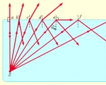
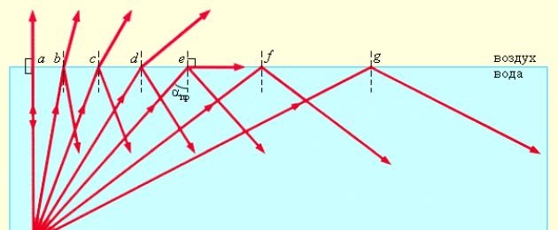
This phenomenon can be observed at angles of incidence that exceed a certain critical angle α p r. This angle is called the limiting angle of total internal reflection (see Fig. 3, 1, 2).
For the angle of incidence α = α p sin β = 1 ; value sin α p p = n 2 n 1< 1 .
Provided that the second medium is air (n 2 ≈ 1), then the equality can be rewritten as: sin α p p = 1 n, where n = n 1 > 1 is the absolute refractive index of the first medium.
Under the conditions of the glass-air interface, where n = 1.5, the critical angle is α p p = 42 °, while for the water-air interface n = 1. 33, and α p p = 48 , 7 ° .

Figure 3. 1 . 2. Total internal reflection of light at the water-air interface; S – point light source.
The phenomenon of total internal reflection is widely used in many optical devices. One of such devices is a fiber light guide - thin, randomly curved threads made of optically transparent material, inside of which light entering the end can spread over enormous distances. This invention became possible only thanks to the correct application of the phenomenon of total internal reflection from lateral surfaces (Fig. 3. 1. 3).
Definition 12
Fiber optics is a scientific and technical direction based on the development and use of optical fibers.

Drawing 3 . 1 . 3 . Propagation of light in a fiber light guide. When the fiber is strongly bent, the law of total internal reflection is violated, and light partially exits the fiber through the side surface.

Drawing 3 . 1 . 4 . Model of reflection and refraction of light.
If you notice an error in the text, please highlight it and press Ctrl+Enter
1. The optical path length is the product of the geometric length d of the path of a light wave in a given medium and the absolute refractive index of this medium n.
2. The phase difference of two coherent waves from one source, one of which travels the path length in a medium with an absolute refractive index, and the other - the path length in a medium with an absolute refractive index:
![]()
where , , λ is the wavelength of light in vacuum.
3. If the optical path lengths of two beams are equal, then such paths are called tautochronous (not introducing a phase difference). In optical systems that produce stigmatic images of a light source, the tautochronicity condition is satisfied by all paths of rays emerging from the same point of the source and converging at the corresponding point of the image.
4. The quantity is called the optical difference in the path of two rays. The stroke difference is related to the phase difference:
If two light rays have common starting and ending points, then the difference in the optical path lengths of such rays is called optical path difference
Conditions for maximums and minimums during interference.
If the oscillations of vibrators A and B are in phase and have equal amplitudes, then it is obvious that the resulting displacement at point C depends on the difference in the path of the two waves.
Maximum conditions:

If the difference in the path of these waves is equal to an integer number of waves (i.e., an even number of half-waves)
Δd = kλ, where k = 0, 1, 2, ..., then an interference maximum is formed at the point of overlap of these waves.
Maximum condition: ![]()
Amplitude of the resulting oscillation A = 2x 0 .
Minimum condition:

If the difference in the path of these waves is equal to an odd number of half-waves, then this means that the waves from vibrators A and B will arrive at point C in antiphase and cancel each other out: the amplitude of the resulting oscillation A = 0.
Minimum condition: ![]()
If Δd is not equal to an integer number of half-waves, then 0< А < 2х 0 .
The phenomenon of light defraction and conditions for its observation.
Initially, the phenomenon of diffraction was interpreted as a wave bending around an obstacle, that is, the penetration of a wave into the region of a geometric shadow. From the point of view of modern science, the definition of diffraction as the bending of light around an obstacle is considered insufficient (too narrow) and not entirely adequate. Thus, diffraction is associated with a very wide range of phenomena that arise during the propagation of waves (if their spatial limitation is taken into account) in inhomogeneous media.
Wave diffraction can manifest itself:
in transforming the spatial structure of waves. In some cases, such a transformation can be considered as waves “bending around” obstacles, in other cases - as an expansion of the angle of propagation of wave beams or their deflection in a certain direction;
in the decomposition of waves according to their frequency spectrum;
in the transformation of wave polarization;
in changing the phase structure of waves.
The most well studied is the diffraction of electromagnetic (in particular, optical) and acoustic waves, as well as gravitational-capillary waves (waves on the surface of a liquid).
One of the important special cases of diffraction is the diffraction of a spherical wave on some obstacles (for example, on a lens frame). This diffraction is called Fresnel diffraction.
Huygens–Fresnel principle.
According to the Huygens-Fresnel principle light wave excited by some source S can be represented as the result of a superposition of coherent secondary waves. Each element of the wave surface S(Fig.) serves as a source of a secondary spherical wave, the amplitude of which is proportional to the size of the element dS.

The amplitude of this secondary wave decreases with distance r from the source of the secondary wave to the observation point according to the law 1/r. Therefore, from each section dS wave surface to the observation point R an elementary vibration comes:
Where ( ωt + α 0) – phase of oscillation at the location of the wave surface S, k− wave number, r− distance from surface element dS to the point P, into which the oscillation occurs. Factor a 0 determined by the amplitude of light vibration at the point where the element is applied dS. Coefficient K depends on the angle φ
between the normal to the site dS and direction to the point R. At φ = 0
this coefficient is maximum, and at φ/2 it is equal to zero.
The resulting oscillation at a point R represents a superposition of vibrations (1) taken for the entire surface S:

This formula is an analytical expression of the Huygens-Fresnel principle.
The lengths of light waves perceived by the eye are very small (of the order of ). Therefore, the propagation of visible light can be considered as a first approximation, abstracting from its wave nature and assuming that light propagates along certain lines called rays. In the limiting case, the corresponding laws of optics can be formulated in the language of geometry.
In accordance with this, the branch of optics in which the finiteness of wavelengths is neglected is called geometric optics. Another name for this section is ray optics.
The basis of geometric optics is formed by four laws: 1) the law of rectilinear propagation of light; 2) the law of independence of light rays; 3) the law of light reflection; 4) the law of light refraction.
The law of rectilinear propagation states that in a homogeneous medium, light travels in a straight line. This law is approximate: when light passes through very small holes, deviations from straightness are observed, the larger the smaller the hole.
The law of independence of light rays states that harriers do not disturb each other when crossing. The intersections of the rays do not prevent each of them from propagating independently of each other. This law is valid only when light intensities are not too high. At intensities achieved with lasers, the independence of the light rays is no longer respected.
The laws of reflection and refraction of light are formulated in § 112 (see formulas (112.7) and (112.8) and the following text).
Geometric optics can be based on the principle established by the French mathematician Fermat in the mid-17th century. From this principle follow the laws of rectilinear propagation, reflection and refraction of light. As formulated by Fermat himself, the principle states that light travels along a path for which it requires the minimum time to travel.

To pass a section of the path (Fig.
115.1) light requires time where v is the speed of light at a given point in the medium.
Replacing v through (see (110.2)), we obtain that Therefore, the time spent by light to travel from point to point 2 is equal to
 (115.1)
A quantity having the dimension of length
called optical path length.
In a homogeneous medium, the optical path length is equal to the product of the geometric path length s and the refractive index of the medium:
According to (115.1) and (115.2)
The proportionality of the travel time to the optical path length L makes it possible to formulate Fermat's principle as follows: light propagates along a path whose optical length is minimal. More precisely, the optical path length must be extreme, i.e., either minimum, or maximum, or stationary - the same for all possible paths. In the latter case, all light paths between two points turn out to be tautochronous (requiring the same time to travel).
Fermat's principle implies the reversibility of light rays. Indeed, the optical path, which is minimal in the case of light propagation from point 1 to point 2, will also be minimal in the case of light propagation in the opposite direction.
Consequently, a ray launched towards a ray that has traveled from point 1 to point 2 will follow the same path, but in the opposite direction.

Using Fermat's principle, we obtain the laws of reflection and refraction of light. Let light fall from point A to point B, reflected from the surface (Fig. 115.2; the direct path from A to B is blocked by an opaque screen E). The medium in which the beam passes is homogeneous. Therefore, the minimum optical path length is reduced to the minimum its geometric length. The geometric length of an arbitrary path is equal to (auxiliary point A is a mirror image of point A). It can be seen from the figure that the path of the ray reflected at point O, for which the angle of reflection is equal to the angle of incidence, has the shortest length. Note that as point O moves away from point O, the geometric length of the path increases indefinitely, so in this case there is only one extremum - the minimum.
Now let's find the point at which the beam must refract, propagating from A to B, so that the optical path length is extreme (Fig. 115.3). For an arbitrary beam, the optical path length is equal to
To find the extreme value, differentiate L with respect to x and equate the derivative to zero)
The factors for are equal respectively. Thus, we obtain the relation
expressing the law of refraction (see formula (112.10)).
Let us consider the reflection from the inner surface of an ellipsoid of revolution (Fig. 115.4; - foci of the ellipsoid). According to the definition of an ellipse, paths, etc., are the same in length.


Therefore, all rays that leave the focus and arrive at the focus after reflection are tautochronous. In this case, the optical path length is stationary. If we replace the surface of the ellipsoid with a MM surface, which has less curvature and is oriented so that the ray emerging from the point after reflection from the MM hits the point, then the path will be minimal. For a surface that has a curvature greater than that of the ellipsoid, the path will be maximum.
Stationarity of optical paths also occurs when rays pass through a lens (Fig. 115.5). The beam has the shortest path in air (where the refractive index is almost equal to unity) and the longest path in glass ( The beam has a longer path in air, but a shorter path in glass. As a result, the optical path lengths for all rays are the same. Therefore the rays are tautochronous and the optical path length is stationary.
Let us consider a wave propagating in an inhomogeneous isotropic medium along rays 1, 2, 3, etc. (Fig. 115.6). We will consider the inhomogeneity to be small enough so that the refractive index can be considered constant on segments of rays of length X.
1) Interference of light.
Interference of light– this is the addition of light waves, in which a characteristic spatial distribution of light intensity (interference pattern) is usually observed in the form of alternating light and dark stripes due to a violation of the principle of addition of intensities.
Interference of light occurs only if the phase difference is constant over time, that is, the waves are coherent.
The phenomenon is observed when two or more light beams are superimposed. The light intensity in the region where the beams overlap has the character of alternating light and dark stripes, with the intensity at the maxima being greater and at the minima less than the sum of the beam intensities. When using white light, the interference fringes appear in different colors of the spectrum.
Interference occurs provided that:
1) The frequencies of the interfering waves are the same.
2) Disturbances, if they are vector in nature, are directed along one straight line.
3) Added oscillations occur continuously throughout the entire observation time.
2) Coherence.
COHERENCE is the coordinated occurrence in space and time of several oscillatory or wave processes, in which the difference in their phases remains constant. This means that waves (sound, light, waves on the surface of water, etc.) propagate synchronously, lagging one another by a very certain amount. When adding coherent oscillations, a interference; the amplitude of the total oscillations is determined by the phase difference.
3) Optical path difference.
Ray path difference, the difference in optical path lengths of two light rays that have common starting and ending points. The concept of path difference plays a fundamental role in describing the interference of light and diffraction of light. Calculations of the distribution of light energy in optical systems are based on calculating the difference in the path of rays (or beams of rays) passing through them.
Optical ray path difference is the difference in the paths that the oscillation travels from the source to the meeting point: φ 1 - φ 2 = 2π/λ 0.
Where a is the wave amplitude, k = 2π / λ is the wave number, λ is the wavelength; I = A 2 - a physical quantity equal to the square of the amplitude of the electric field of the wave, i.e. intensity, and Δ = r 2 - r 1 - the so-called path difference.
4) Distribution of light intensity in the interference field.
The interference maximum (light stripe) is achieved at those points in space at which Δ = mλ (m = 0, ±1, ±2, ...), where Δ = r 2 – r 1 is the so-called path difference. In this case, I max = (a 1 + a 2) 2 > I 1 + I 2. The interference minimum (dark band) is achieved at Δ = mλ + λ / 2. Minimum intensity value I min = (a 1 – a 2) 2< I 1 + I 2 . На рис. 3.7.4 показано распределение интенсивности света в интерференционной картине в зависимости от разности хода Δ.
 Intensity distribution in the interference pattern. Integer m is the order of the interference maximum.
The maxima are located at those points for which the difference in the path of the rays fits an integer number of wavelengths (an even number of half-waves), the minima are an odd number of half-waves.
Integer m – maximum order.
5) Interference in thin plates. Interferometers.
Interference in thin films. It is often observed that thin transparent films acquire a rainbow coloration - this phenomenon is caused by the interference of light. Let light from a point source S fall on the surface of a transparent film. The rays are partially reflected from the surface of the film facing the source, and partially pass into the thickness of the film, reflected from its other surface and, refracted again, come out. Thus, in the region above the film surface there is a superposition of two waves formed as a result of the reflection of the initial wave from both surfaces of the film. To observe the interference pattern, you need to collect the interference rays, for example, by placing a collecting lens in their path, and behind it at some distance an observation screen.
It can be deduced that the optical path difference is equal to O. r. X. = 2h√(n 2 -sin 2 i) + λ/2, where h is the film thickness, i is the angle of incidence of the rays, n is the refractive index of the film substance, λ is the wavelength.
Thus, for a homogeneous film, the optical path difference depends on two factors: the angle of incidence of the beam i and the film thickness h at the point of incidence of the beam.
 Plane-parallel film. Since the film thickness is the same everywhere, the r.r.x. depends only on the angle of incidence. Therefore, for all pairs of rays with the same inclination angle, the o.r.x. are the same, and as a result of the interference of these rays, a line appears on the screen along which the intensity is constant. As the angle of incidence increases, the path difference continuously decreases, periodically becoming equal to either an even or an odd number of half-waves, therefore alternating light and dark stripes is observed.
Heterogeneous film. With increasing film thickness, o.r.x. rays continuously grows, alternately becoming equal to either an even or an odd number of half-waves, therefore, an alternation of dark and light stripes is observed - stripes of equal thickness, formed by rays coming from places with the same film thickness.
 Interferometer– a measuring device that uses wave interference. Optical interferometers are the most widely used. They are used to measure spectral line wavelengths, refractive index transparent media, absolute and relative lengths, angular sizes of stars etc., for quality control of optical parts and their surfaces, etc.
Principle The actions of all interferometers are the same, and they differ only in the methods of producing coherent waves and in what quantity is directly measured. A beam of light, using one or another device, is spatially divided into two or more coherent beams, which pass through different optical paths and are then brought together. At the point where the beams converge, an interference pattern is observed, the appearance of which, i.e., the shape and relative position of the interference maxima and minima, depends on the method of dividing the light beam into coherent beams, on the number of interfering beams, the difference in their optical paths (optical path difference), the relative intensity, source size, spectral composition of light.
Diffraction of light. Huygens-Fresnel principle. Fresnel and Fraunhofer diffraction. Diffraction grating. Diffraction spectra and spectrographs. X-ray diffraction in crystals. Wulff-Bragg formula.
1) Diffraction of light.
Diffraction light is the phenomenon of deviation of light from the rectilinear direction of propagation when passing near obstacles.
Under certain conditions, light can enter the geometric shadow area. If there is a round obstacle in the path of a parallel light beam (a round disk, a ball or a round hole in an opaque screen), then on the screen located at a sufficiently large distance from the obstacle, diffraction pattern– a system of alternating light and dark rings. If the obstacle is linear (slit, thread, edge of the screen), then a system of parallel diffraction fringes appears on the screen.
2) Huygens-Fresnel principle.
The phenomenon of diffraction is explained using Huygens' principle, according to which each point to which a wave reaches serves as the center of secondary waves, and the envelope of these waves sets the position of the wave front at the next moment in time.
Let a plane wave be normally incident on a hole in an opaque screen. Each point of the wave front section isolated by the hole serves as a source of secondary waves  (in a homogeneous isotopic medium they are spherical).
Having constructed the envelope of secondary waves for a certain moment in time, we see that the wave front enters the region of the geometric shadow, i.e. the wave goes around the edges of the hole.
Fresnel put a physical meaning into Huygens' principle, supplementing it with the idea of interference of secondary waves.
When considering diffraction, Fresnel proceeded from several basic principles, accepted without proof. The set of these statements is called the Huygens–Fresnel principle.
According to Huygens' principle, each point on the wave front can be considered a source of secondary waves.
Fresnel significantly developed this principle.
· All secondary sources of a wave front emanating from one source are coherent with each other.
· Equal areas of the wave surface emit equal intensities (powers).
· Each secondary source emits light predominantly in the direction of the outer normal to the wave surface at that point. The amplitude of secondary waves in the direction making an angle α with the normal is smaller, the larger the angle α, and is equal to zero at .
· For secondary sources, the principle of superposition is valid: the radiation of some sections of the wave surface does not affect the radiation of others (if part of the wave surface is covered with an opaque screen, secondary waves will be emitted by open sections as if there was no screen).
The Huygens-Fresnel principle is formulated as follows: Each element of the wave front can be considered as the center of a secondary disturbance generating secondary spherical waves, and the resulting light field at each point in space will be determined by the interference of these waves.
3) Fresnel and Fraunhofer diffraction.
Fresnel proposed dividing the wave surface of the incident wave at the location of the obstacle into ring zones (Fresnel zones) according to the following rule: the distance from the boundaries of adjacent zones to point P should differ by half the wavelength, i.e. ![]() , where L is the distance from the screen to the observation point.
, where L is the distance from the screen to the observation point. 
It is easy to find the radii ρ m of the Fresnel zones: 
So in optics λ<< L, вторым членом под корнем можно пренебречь. Количество зон Френеля, укладывающихся на отверстии, определяется его радиусом R: Здесь m – не обязательно целое число.
Fresnel diffraction is the diffraction of a spherical light wave on an inhomogeneity (for example, a hole), the size of which is comparable to the diameter of one of the Fresnel zones.
For practice, the most interesting case is the diffraction of light, when an obstacle leaves only a small part of the 1st Fresnel zone open. This case is realized under the condition ![]()
i.e., the diffraction pattern from small obstacles should in this case be observed at very large distances. For example, if R = 1 mm, λ = 550 nm (green light), then the distance L to the viewing plane should be significantly greater than 2 meters (i.e., at least 10 meters or more). Rays directed to a distant observation point from various elements of the wave front can practically be considered parallel. This case of diffraction is called diffraction in parallel rays or Fraunhofer diffraction. If a collecting lens is placed on the path of the rays behind an obstacle, then a parallel beam of rays, diffracted at the obstacle at an angle θ, will be collected at some point of the focal plane. Therefore, any point in the focal plane of a lens is equivalent to a point at infinity in the absence of a lens.
4) Diffraction grating.
Diffraction grating- an optical device operating on the principle of light diffraction, is a collection of a large number of regularly spaced strokes (slots, protrusions) applied to a certain surface.
· Reflective: Strokes are applied to a mirror (metal) surface, and observation is carried out in reflected light
· Transparent: Strokes are applied to a transparent surface (or cut out in the form of slits on an opaque screen), observation is carried out in transmitted light.
The distance through which the lines on the grating are repeated is called the period of the diffraction grating. Designated by letter d.
If the number of strokes is known ( N) per 1 mm of grating, then the grating period is found using the formula: d = 1 / N mm.
The conditions for the main diffraction maxima observed at certain angles are as follows:
Where d- grating period, α - maximum angle of a given color, k- order of maximum,
λ - wavelength.
Description of the phenomenon: The front of the light wave is divided by the grating bars into separate beams of coherent light. These beams undergo diffraction by the streaks and interfere with each other. Since each wavelength has its own diffraction angle, white light is decomposed into a spectrum.
5) Diffraction spectra and spectrographs.
The diffraction spectrum is obtained when light passes through a large number of small holes and slits, i.e. through diffraction gratings or when reflected from them.
In the diffraction spectrum, the deviation of rays is strictly proportional to the wavelength, so that ultraviolet and violet rays, as having the shortest waves, are rejected the least, and red and infrared rays, as having the longest waves, are rejected the most. The diffraction spectrum is most extended towards red rays.
Spectrograph is a spectral device in which the radiation receiver records almost simultaneously the entire spectrum unfolded in the focal plane of the optical system. Photographic materials and multi-element photodetectors serve as radiation detectors in the spectrograph.
The spectrograph has three main parts: a collimator consisting of a lens with a focal length f 1 and a slit installed at the focal point of the lens; a dispersive system consisting of one or more refractive prisms; and a camera consisting of a lens with a focal length f 2 and a photographic plate located in the focal plane of the lens.
6) X-ray diffraction in crystals.
X-ray diffraction, scattering of X-rays by crystals (or molecules of liquids and gases), in which secondary deflected beams of the same wavelength arise from the initial beam of rays, resulting from the interaction of primary X-rays with electrons of the substance; the direction and intensity of the secondary beams depend on the structure of the scattering object. Diffracted beams make up part of the total X-ray radiation scattered by matter.
The crystal is natural three-dimensional diffraction grating for x-rays, because the distance between scattering centers (atoms) in a crystal is of the same order as the wavelength of X-rays (~1Å=10 -8 cm). X-ray diffraction by crystals can be considered as the selective reflection of X-rays from systems of atomic planes of the crystal lattice. The direction of the diffraction maxima satisfies three conditions simultaneously:
a(cos a - cos a 0) = N l,
b(cos b - cos b 0) = K l,
With(cos g - cos g 0) = L l.
Here A, b, With- periods crystal lattice along its three axes; a 0 , b 0 , g 0 are the angles formed by the incident, and a, b, g - scattered rays with the crystal axes; l is the wavelength of X-rays, N, TO, L- whole numbers. These equations are called Laue equations. The diffraction pattern is obtained either from a stationary crystal using X-ray radiation with a continuous spectrum, or from a rotating or oscillating crystal (angles a 0, b 0 change, and g 0 remains constant), illuminated by monochromatic X-ray radiation (l - constant), or from a polycrystal , illuminated by monochromatic radiation.
7) Wulff-Bragg formula.
This is the condition that determines the position of the interference maxima of X-rays scattered by the crystal without changing their length. According to the Bragg-Wulf theory, maxima arise when X-rays are reflected from a system of parallel crystallographic planes, when the rays reflected by different planes of this system have a path difference equal to an integer number of wavelengths.
Where d- interplanar distance, θ - grazing angle, i.e. the angle between the reflecting plane and the incident beam (diffraction angle), l - x-ray wavelength and m- reflection order, i.e. a positive integer.
Polarization of light. Malus's law. Brewster's Law. Birefringence in uniaxial crystals. Rotation of the plane of polarization. Methods of polarization analysis of rocks. Normal and anomalous dispersion of light. Scattering of light. External photoeffect. “Red border” of the photoelectric effect.
1) Polarization of light.
Polarization of light- this is the orderliness in the orientation of the vectors of intensity of the electric E and magnetic H fields of a light wave in a plane perpendicular to the light beam. There is linear polarization of light, when E maintains a constant direction (the plane of polarization is the plane in which E and the light beam lie), elliptical polarization of light, in which the end E describes an ellipse in a plane perpendicular to the beam, and circular polarization of light (end E describes a circle ).
Occurs when light hits a surface at a certain angle, is reflected and becomes polarized. Polarized light also propagates freely in space, like ordinary sunlight, but mainly in two directions - horizontal and vertical. The “vertical” component brings useful information to the human eye, allowing it to recognize colors and contrast. And the “horizontal” component creates “optical noise” or glare.
2) Malus's law. Brewster's Law.
Malus's law- dependence of the intensity of linearly polarized light after it passes through the polarizer on the angle between the polarization planes of the incident light and the polarizer. ![]() Where I 0 - intensity of light incident on the polarizer, I- intensity of light emerging from the polarizer.
Where I 0 - intensity of light incident on the polarizer, I- intensity of light emerging from the polarizer.
Brewster's Law- a law of optics that expresses the relationship of the refractive index with the angle at which light reflected from the interface will be completely polarized in a plane perpendicular to the plane of incidence, and the refracted beam is partially polarized in the plane of incidence, and the polarization of the refracted beam reaches its greatest value. It is easy to establish that in this case the reflected and refracted rays are mutually perpendicular. The corresponding angle is called Brewster's angle. tan φ = n where the refractive index of the second medium relative to the first sin φ/sin r = n (r is the angle of refraction) and φ is the angle of incidence (Brewster angle).
3) Birefringence in uniaxial crystals.
Birefringence- the effect of splitting a light beam into two components in anisotropic media. First discovered on an Iceland spar crystal. If a ray of light falls perpendicular to the surface of the crystal, then on this surface it is split into two rays. The first ray continues to propagate straight and is called ordinary, while the second ray deviates to the side, violating the usual law of refraction of light, and is called extraordinary.
Birefringence can also be observed when a beam of light is incident obliquely on the surface of a crystal. In Iceland spar and some other crystals there is only one direction along which dilation does not occur. It is called the optical axis of the crystal, and such crystals are uniaxial.
4) Rotation of the plane of polarization.
Rotation of the plane of polarization light - rotation of the plane of polarization of linearly polarized light as it passes through matter. Rotation of the plane of polarization is observed in media with circular birefringence.
A linearly polarized beam of light can be thought of as the result of the addition of two rays propagating in the same direction and polarized in a circle with opposite directions of rotation. If such two beams propagate in a body at different speeds, this leads to a rotation of the plane of polarization of the total beam. The rotation of the plane of polarization can be caused either by the internal structure of the substance or by an external magnetic field.
If you pass a ray of sunlight through a small hole made in an opaque plate behind which an Iceland spar crystal is placed, then two rays of equal light intensity will emerge from the crystal. The solar ray was divided, with a slight loss of luminous intensity, in the crystal into two rays of equal luminous intensity, but in some properties different from the unchanged solar ray and from each other.
5) Methods of polarization analysis of rocks.
Seismic exploration - a geophysical method for studying geological objects using elastic vibrations - seismic waves. This method is based on the fact that the speed of propagation and other characteristics of seismic waves depend on the properties of the geological environment in which they propagate: on the composition of rocks, their porosity, fracturing, fluid saturation, stress state and temperature conditions of occurrence. The geological environment is characterized by an uneven distribution of these properties, that is, heterogeneity, which manifests itself in reflection, refraction, refraction, diffraction and absorption of seismic waves. The study of reflected, refracted, refracted and other types of waves in order to identify the spatial distribution and quantify the elastic and other properties of the geological environment constitutes the content of seismic exploration methods and determines their diversity.
Vertical seismic profiling- This is a type of 2D seismic exploration, during which seismic wave sources are located on the surface and receivers are placed in a drilled well.
Acoustic logging- methods for studying the properties of rocks by measuring in a borehole the characteristics of elastic waves of ultrasonic (above 20 kHz) and sound frequencies. During acoustic logging, elastic vibrations are excited in a well, which propagate in it and in the surrounding rocks and are perceived by receivers located in the same environment.
6) Normal and anomalous dispersion of light.
Light dispersion is the dependence of the refractive index of a substance on the frequency of the light wave. This relationship is not linear or monotonic. Areas of value ν in which (or ) correspond normal dispersion light (with increasing frequency ν the refractive index n increases). Normal dispersion is observed in substances that are transparent to light. For example, ordinary glass is transparent to visible light, and in this frequency region there is normal dispersion of light in glass. The “decomposition” of light by the glass prism of monochromators is based on the phenomenon of normal dispersion.
The variance is called abnormal, if (or)
those. As frequency ν increases, the refractive index n decreases. Anomalous dispersion is observed in frequency regions corresponding to bands of intense light absorption in a given medium. For example, ordinary glass exhibits anomalous dispersion in the infrared and ultraviolet parts of the spectrum.
7) Scattering of light.
Light Scattering- scattering of electromagnetic waves in the visible range during their interaction with matter. In this case, a change occurs in the spatial distribution, frequency, and polarization of optical radiation, although scattering is often understood as only a transformation of the angular distribution of the light flux.
8) External photoeffect. “Red border” of the photoelectric effect.
Photo effect- this is the emission of electrons by a substance under the influence of light (and, generally speaking, any electromagnetic radiation). In condensed substances (solid and liquid) there is an external and internal photoelectric effect.
Laws of the photoelectric effect:
The formulation of the 1st law of the photoelectric effect: the number of electrons emitted by light from the surface of a metal in 1 s is directly proportional to the light intensity.
According to the 2nd law of the photoelectric effect, the maximum kinetic energy of electrons ejected by light will increase linearly with the frequency of light and does not depend on its intensity.
3rd law of the photoelectric effect: for each substance there is a red limit of the photoelectric effect, that is, the minimum light frequency ν0 (or maximum wavelength y0), at which the photoelectric effect is still possible, and if ν<ν0 , то фотоэффект уже не происходит .
External photoeffect(photoelectron emission) is the emission of electrons by a substance under the influence of electromagnetic radiation. Electrons emitted from a substance due to the external photoelectric effect are called photoelectrons, and the electric current generated by them during ordered movement in an external electric field is called photocurrent.
Photocathode is an electrode of a vacuum electronic device that is directly exposed to electromagnetic radiation and emits electrons under the influence of this radiation.
The dependence of spectral sensitivity on the frequency or wavelength of electromagnetic radiation is called the spectral characteristic of the photocathode.
Laws of external photoelectric effect
1. Stoletov’s law: with a constant spectral composition of electromagnetic radiation incident on the photocathode, the saturation photocurrent is proportional to the energy illumination of the cathode (in other words: the number of photoelectrons knocked out of the cathode in 1 s is directly proportional to the radiation intensity):
And
2. The maximum initial speed of photoelectrons does not depend on the intensity of the incident light, but is determined only by its frequency.
3. For each photocathode there is a red limit of the photoelectric effect, that is, the minimum frequency of electromagnetic radiation ν 0 at which the photoelectric effect is still possible.
"Red" border of the photoelectric effect- the minimum frequency of light at which the external photoelectric effect is still possible, that is, the initial kinetic energy of photoelectrons is greater than zero. The frequency depends only on the work function of the electron: where A is the work function for a specific photocathode, and h- Planck's constant. Work function A depends on the material of the photocathode and the condition of its surface. The emission of photoelectrons begins as soon as light with a frequency of .
The structure of the atom. Bohr's postulates. Features of the movement of quantum particles. De Broglie's hypothesis. Heisenberg uncertainty principle. Quantum numbers. Pauli's principle. The atomic nucleus, its composition and characteristics. Nucleon binding energy in the nucleus and mass defect. Mutual transformations of nucleons. Natural and artificial radioactivity. Chain reaction of uranium fission. Thermonuclear fusion and the problem of controlled thermonuclear reactions.
1) The structure of the atom.
Atom- the smallest chemically indivisible part of a chemical element, which is the carrier of its properties.
An atom consists of an atomic nucleus and a surrounding electron cloud. The nucleus of an atom consists of positively charged protons and electrically neutral neutrons, while the cloud surrounding it consists of negatively charged electrons. If the number of protons in the nucleus coincides with the number of electrons, then the atom as a whole turns out to be electrically neutral. Otherwise, it has some positive or negative charge and is called an ion. Atoms are classified according to the number of protons and neutrons in the nucleus: the number of protons determines whether the atom belongs to a certain chemical element, and the number of neutrons determines the isotope of this element.
Atoms of different types in different quantities, connected by interatomic bonds, form molecules.
2) Bohr's postulates.
These postulates read:
1.in an atom there are stationary orbits in which the electron does not emit or absorb energy,
2. the radius of stationary orbits is discrete; its values must satisfy the conditions for quantizing the angular momentum of the electron: m v r = n, where n is an integer,
3. when moving from one stationary orbit to another, an electron emits or absorbs a quantum of energy, and the magnitude of the quantum is exactly equal to the difference in the energies of these levels: hn = E 1 – E 2.
3) Features of the movement of quantum particles.
Quantum particles- these are elementary particles - referring to micro-objects on a subnuclear scale that cannot be split into their component parts.
In quantum mechanics, particles do not have a specific coordinate and we can only talk about the probability of finding a particle in a certain region of space. The state of a particle is described by a wave function, and the dynamics of a particle (or system of particles) is described by the Schrödinger equation. The Schrödinger equation and its solutions: describe the energy levels of a particle; describe wave functions;
describe the energy levels of a particle when there is not only a magnetic field, but also an electric one; describe the energy levels of a particle in two-dimensional space.
The Schrödinger equation for one particle has the form 
where m is the mass of the particle, E is its total energy, V(x) is the potential energy, and y is the quantity describing the electron wave.
4) De Broglie's hypothesis.
According to de Broglie's hypothesis, each material particle has wave properties, and the relationships connecting the wave and corpuscular characteristics of the particle remain the same as in the case of electromagnetic radiation. Let us recall that the energy and momentum of a photon are related to the circular frequency and wavelength by the relations ![]()
According to de Broglie's hypothesis, a moving particle with energy and momentum corresponds to a wave process, the frequency of which is equal to and the wavelength
As is known, a plane wave with a frequency propagating along the axis can be represented in complex form where is the amplitude of the wave, and is the wave number.
According to de Broglie's hypothesis, a free particle with energy and momentum moving along the axis corresponds to a plane wave ![]() propagating in the same direction and describing the wave properties of the particle. This wave is called the de Broglie wave. Relations connecting the wave and corpuscular properties of a particle
propagating in the same direction and describing the wave properties of the particle. This wave is called the de Broglie wave. Relations connecting the wave and corpuscular properties of a particle ![]()
where the momentum of the particle and is the wave vector are called the de Broglie equations.
5) Heisenberg uncertainty principle.
Experimental studies of the properties of microparticles (atoms, electrons, nuclei, photons, etc.) have shown that the accuracy of determining their dynamic variables (coordinates, kinetic energy, momentum, etc.) is limited and is regulated by W. Heisenberg’s uncertainty principle. According to this principle, the dynamic variables characterizing the system can be divided into two (mutually complementary) groups:
1) temporal and spatial coordinates ( t And q);
2) impulses and energy ( p And E).
In this case, it is impossible to simultaneously determine variables from different groups with any desired degree of accuracy (for example, coordinates and impulses, time and energy). This is not due to the limited resolution of instruments and experimental technology, but reflects a fundamental law of nature. Its mathematical formulation is given by the relations: where D q, D p, D E, D t- uncertainty (error) in measuring coordinates, momentum, energy and time, respectively; h- Planck's constant.
Usually the energy value of a microparticle is indicated quite accurately, since this value is relatively easily determined experimentally.
6) Quantum numbers.
Quantum number in quantum mechanics - a numerical value (integer (0, 1, 2,...) or half-integer (1 / 2, 3 / 2, 5 / 2,...) numbers defining possible discrete values of physical quantities) of any a quantized variable of a microscopic object (elementary particle, nucleus, atom, etc.), characterizing the state of the particle. Specifying quantum numbers completely characterizes the state of the particle.
Some quantum numbers are associated with motion in space and characterize the spatial distribution of the particle's wave function. This is, for example, radial (main) ( n r), orbital ( l) and magnetic ( m) quantum numbers of an electron in an atom, which are defined as the number of nodes of the radial wave function, the value of the orbital angular momentum and its projection onto a given axis, respectively.
7) Pauli's principle.
Pauli principle(prohibition principle) is one of the fundamental principles of quantum mechanics, according to which two or more identical fermions (elementary particles that make up matter or a particle with a half-integer spin value (the intrinsic angular momentum of elementary particles)) cannot simultaneously be in the same quantum state.
The Pauli principle can be formulated as follows: within one quantum system, only one particle can be in a given quantum state, the state of the other must differ in at least one quantum number.
8) The atomic nucleus, its composition and characteristics.
Atomic nucleus- the central part of an atom, in which the bulk of its mass is concentrated and the structure of which determines the chemical element to which the atom belongs.
Atomic nucleus consists of of nucleons - positively charged protons and neutral neutrons, which are connected to each other through strong interaction. The proton and neutron have their own angular momentum (spin), equal to and associated with it magnetic moment.
The atomic nucleus, considered as a class of particles with a certain number of protons and neutrons, is usually called a nuclide.
The number of protons in a nucleus is called its charge number - this number is equal to the atomic number of the element to which the atom belongs in the periodic table. The number of protons in the nucleus completely determines the structure of the electron shell of a neutral atom and, thus, the chemical properties of the corresponding element. The number of neutrons in a nucleus is called its isotopic number. Nuclei with the same number of protons and different numbers of neutrons are called isotopes. Nuclei with the same number of neutrons but different numbers of protons are called isotones.
The total number of nucleons in a nucleus is called its mass number (obviously) and is approximately equal to the average mass of an atom shown in the periodic table.
The mass of the nucleus m i is always less than the sum of the masses of the particles included in it. This is due to the fact that when nucleons combine into a nucleus, the binding energy of nucleons with each other is released. The rest energy of a particle is related to its mass by the relation E 0 = mc 2 . Consequently, the energy of the nucleus at rest is less than the total energy of interacting nucleons at rest by the amount E st = c 2 (-m i ). This value is binding energy of nucleons in the nucleus It is equal to the work that needs to be done to separate the nucleons forming the nucleus and remove them from each other at such distances that they practically do not interact with each other. The quantity Δ=-n is called core mass defect.The mass defect is related to the binding energy by the relation Δ=E light /c 2.
Mass defect- the difference between the rest mass of the atomic nucleus of a given isotope, expressed in atomic mass units, and the sum of the rest masses of its constituent nucleons. Usually designated .
According to Einstein's relation, the mass defect and the binding energy of nucleons in the nucleus are equivalent:
Where Δ m- mass defect and With- speed of light in vacuum. The mass defect characterizes the stability of the nucleus.
10) Mutual transformations of nucleons.
Beta radiation is a stream of β - particles emitted by atomic nuclei during the β - decay of radioactive isotopes. β-decay is the radioactive decay of an atomic nucleus, accompanied by the emission of an electron or positron from the nucleus. This process is caused by the spontaneous transformation of one of the nucleons of the nucleus into a nucleon of a different kind, namely: the transformation of either a neutron (n) into a proton (p), or a proton into a neutron. Electrons and positrons emitted during beta decay are collectively called beta particles. Mutual transformations of nucleons are accompanied by the appearance of another particle - a neutrino (n) in the case of β + - decay or an antineutrino in the case of β - - decay.
11) Natural and artificial radioactivity.
Radioactivity - spontaneous transformation of some nuclei into others, accompanied by the emission of various particles or nuclei.
Natural radioactivity observed in nuclei existing in natural conditions.
Artificial radioactivity- for nuclei artificially obtained through nuclear reactions
12) Chain reaction of uranium fission.
Fission reactions are a process in which an unstable nucleus splits into two large fragments of comparable masses.
When uranium is bombarded with neutrons, elements of the middle part of the periodic table arise - radioactive isotopes of barium (Z = 56), krypton (Z = 36), etc.
Uranium occurs in nature in the form of two isotopes: (99.3%) and (0.7%). When bombarded by neutrons, the nuclei of both isotopes can split into two fragments. In this case, the fission reaction occurs most intensely with slow (thermal) neutrons, while nuclei enter into a fission reaction only with fast neutrons with an energy of the order of 1 MeV.
The main interest for nuclear energy is the fission reaction of a nucleus. Currently, about 100 different isotopes with mass numbers from approximately 90 to 145 are known, resulting from the fission of this nucleus. Two typical fission reactions of this nucleus are:  As a result of nuclear fission initiated by a neutron, new neutrons are produced that can trigger fission reactions of other nuclei. The fission products of uranium-235 nuclei can also be other isotopes of barium, xenon, strontium, rubidium, etc.
13) Thermonuclear fusion and the problem of controlled thermonuclear reactions.
Thermonuclear reaction(synonym: nuclear fusion reaction) is a type of nuclear reaction in which light atomic nuclei combine to form heavier nuclei. The use of nuclear fusion reaction as a practically inexhaustible source of energy is associated primarily with the prospect of mastering controlled fusion technology.
Controlled thermonuclear fusion(CBF) is the synthesis of heavier atomic nuclei from lighter ones in order to obtain energy, which, unlike explosive thermonuclear fusion (used in thermonuclear weapons), is controlled in nature. Controlled thermonuclear fusion differs from traditional nuclear energy in that the latter uses a decay reaction, during which lighter nuclei are produced from heavy nuclei. The main nuclear reactions planned to be used to achieve controlled thermonuclear fusion will use deuterium (2 H) and tritium (3 H), and in the longer term helium-3 (3 He) and boron-11 (11 B).
Controlled thermonuclear fusion is possible if two criteria are met simultaneously:
· The speed of collision of nuclei corresponds to the temperature of the plasma:
Compliance with Lawson's criterion:
(for D-T reaction)
where is the density of high-temperature plasma, is the plasma retention time in the system.
The speed of a particular thermonuclear reaction mainly depends on the value of these two criteria.
At present (2010), controlled thermonuclear fusion has not yet been carried out on an industrial scale.
From (4) it follows that the result of the addition of two coherent light rays depends on both the path difference and the light wavelength. The wavelength in vacuum is determined by the quantity , where With=310 8 m/s is the speed of light in vacuum, and  – frequency of light vibrations. The speed of light v in any optically transparent medium is always less than the speed of light in vacuum and the ratio
  called optical density environment. This value is numerically equal to the absolute refractive index of the medium.
The frequency of light vibrations determines color light wave. When moving from one environment to another, the color does not change. This means that the frequency of light vibrations in all media is the same. But then, when light passes, for example, from a vacuum into a medium with a refractive index n the wavelength must change  , which can be converted like this:
 ,
,
where 0 is the wavelength in vacuum. That is, when light passes from a vacuum into an optically denser medium, the wavelength of the light is decreases V n once. On the geometric path  in an environment with optical density n will fit
 waves (5)
Magnitude  called optical path length light in matter:
Optical path length  light in a substance is the product of its geometric path length in this medium and the optical density of the medium:
 .
.
In other words (see relation (5)):
The optical path length of light in a substance is numerically equal to the path length in a vacuum, on which the same number of light waves fits as on the geometric length in the substance.
Because the result of interference depends on phase shift between interfering light waves, then it is necessary to evaluate the result of interference optical path difference between two rays
 ,
,
which contains the same number of waves regardless on the optical density of the medium.
2.1.3.Interference in thin films
The division of light beams into “halves” and the appearance of an interference pattern is also possible under natural conditions. A natural “device” for dividing light beams into “halves” are, for example, thin films. Figure 5 shows a thin transparent film with a thickness  , to which at an angle
  A beam of parallel light rays falls (a plane electromagnetic wave). Beam 1 is partially reflected from the upper surface of the film (beam 1), and partially refracted into the film

ki at the angle of refraction  . The refracted beam is partially reflected from the lower surface and exits the film parallel to beam 1 (beam 2). If these rays are directed at a collecting lens L, then on the screen E (in the focal plane of the lens) they will interfere. The result of interference will depend on optical the difference in the path of these rays from the “division” point
  to the meeting point
  . From the figure it is clear that geometric the difference in the path of these rays is equal to the difference geom . =ABC–AD.
The speed of light in air is almost equal to the speed of light in vacuum. Therefore, the optical density of air can be taken as unity. If the optical density of the film material n, then the optical path length of the refracted ray in the film ABCn. In addition, when beam 1 is reflected from an optically denser medium, the phase of the wave changes to the opposite, that is, half a wave is lost (or vice versa, gained). Thus, the optical path difference of these rays should be written in the form
wholesale . = ABCn – AD / . (6)
From the figure it is clear that ABC = 2d/cos r, A
AD = ACsin i = 2dtg rsin i.
If we put the optical density of air n V=1, then known from the school course Snell's law gives for the refractive index (optical density of the film) the dependence
 . (6a)
Substituting all this into (6), after transformations we obtain the following relation for the optical path difference of the interfering rays:
Because When beam 1 is reflected from the film, the phase of the wave changes to the opposite, then conditions (4) for the maximum and minimum interference are reversed:
- condition max
- condition min. (8)

It can be shown that when passing light through a thin film also produces an interference pattern. In this case, there will be no loss of half a wave, and conditions (4) are met.
Thus, the conditions max And min upon interference of rays reflected from a thin film, are determined by relation (7) between four parameters -  It follows that:
1) in “complex” (non-monochromatic) light, the film will be painted with the color whose wavelength  satisfies the condition max;
2) changing the inclination of the rays (  ), you can change the conditions max, making the film either dark or light, and by illuminating the film with a diverging beam of light rays, you can get stripes« equal slope", corresponding to the condition max by angle of incidence
  ;
;
3) if the film has different thicknesses in different places (  ), then it will be visible strips of equal thickness, on which the conditions are met max by thickness
  ;
;
4) under certain conditions (conditions min when the rays are incident vertically on the film), the light reflected from the surfaces of the film will cancel each other out, and reflections there won't be any from the film.
- In contact with 0
- Google+ 0
- OK 0
- Facebook 0