The propagation of a beam in an optically homogeneous medium is rectilinear, but in nature there are a number of phenomena where deviations from this condition can be observed.
Diffraction– the phenomenon of light waves bending around encountered obstacles. In school physics, two diffraction systems are studied (systems in which diffraction is observed during the passage of a beam):
- diffraction by a slit (rectangular hole)
- grating diffraction (a set of slits equally spaced from each other)
— diffraction at a rectangular hole (Fig. 1).
Rice. 1. Slit diffraction
Let a plane be given with a slit of width , onto which a beam of light A falls at a right angle. Most of the light passes onto the screen, but some of the rays diffract at the edges of the slit (i.e., deviate from their original direction). These rays then interact with each other to form a diffraction pattern on the screen (alternating bright and dark areas). Consideration of the laws of interference is quite complex, so we will limit ourselves to the main conclusions.
The resulting diffraction pattern on the screen consists of alternating areas with diffraction maxima (the brightest areas) and diffraction minima (the darkest areas). This pattern is symmetrical relative to the central light beam. The position of the maxima and minima is described by the angle relative to the vertical at which they are visible and depends on the size of the slit and the wavelength of the incident radiation. The position of these areas can be found using a number of relationships:
- for diffraction maxima
The zero diffraction maximum is the central point on the screen under the slit (Fig. 1).
- for diffraction minima
Conclusion: according to the conditions of the problem, it is necessary to find out: the maximum or minimum of diffraction must be found and the corresponding relation (1) or (2) must be used.
Diffraction by a diffraction grating.
A diffraction grating is a system consisting of alternating slits equally spaced from each other (Fig. 2).

Rice. 2. Diffraction grating (rays)
Just as for the slit, a diffraction pattern will be observed on the screen after the diffraction grating: alternating light and dark areas. The entire picture is the result of the interference of light rays with each other, but the picture from one slit will be affected by rays from other slits. Then the diffraction pattern should depend on the number of slits, their sizes and proximity.
Let's introduce a new concept - diffraction grating constant:
Then the positions of the diffraction maxima and minima:
- for the main diffraction maxima(Fig. 3)

the phenomenon of dispersion when passing white light through a prism (Fig. 102). When leaving the prism, white light is decomposed into seven colors: red, orange, yellow, green, blue, indigo, violet. Red light deviates the least, violet light deviates the most. This suggests that glass has the highest refractive index for violet light, and the lowest for red light. Light with different wavelengths propagates in a medium at different speeds: violet with the lowest, red with the highest, since n= c/v,
As a result of the passage of light through a transparent prism, an ordered arrangement of monochromatic electromagnetic waves in the optical range is obtained - a spectrum.
All spectra are divided into emission spectra and absorption spectra. The emission spectrum is created by luminous bodies. If a cold, non-emitting gas is placed in the path of the rays incident on the prism, then dark lines appear against the background of the continuous spectrum of the source.
Light
Light is transverse waves
An electromagnetic wave is the propagation of an alternating electromagnetic field, and the strengths of the electric and magnetic fields are perpendicular to each other and to the line of propagation of the wave: electromagnetic waves are transverse.
Polarized light
Polarized light is light in which the directions of oscillations of the light vector are ordered in some way.
Light falls from a medium with a large display. Refractions into a medium with less
Methods for producing linear polarized light
Birefringent crystals are used to produce linearly polarized light in two ways. In the first one they use crystals that do not have dichroism; They are used to make prisms composed of two triangular prisms with the same or perpendicular orientation of the optical axes. In them, either one beam is deflected to the side, so that only one linearly polarized beam emerges from the prism, or both beams come out, but separated by a large angle. In the second method is used strongly dichroic crystals, in which one of the rays is absorbed, or thin films - polaroids in the form of sheets of large area.
Brewster's Law
Brewster's law is a law of optics that expresses the relationship of the refractive index with the angle at which light reflected from the interface will be completely polarized in a plane perpendicular to the plane of incidence, and the refracted beam is partially polarized in the plane of incidence, and the polarization of the refracted beam reaches its greatest value. It is easy to establish that in this case the reflected and refracted rays are mutually perpendicular. The corresponding angle is called Brewster's angle.
Brewster's law: , where n21 is the refractive index of the second medium relative to the first, θBr is the angle of incidence (Brewster angle)
Law of Light Reflection
The law of light reflection - establishes a change in the direction of travel of a light ray as a result of a meeting with a reflecting (mirror) surface: the incident and reflected rays lie in the same plane with the normal to the reflecting surface at the point of incidence, and this normal divides the angle between the rays into two equal parts. The widely used but less precise formulation "angle of incidence equals angle of reflection" does not indicate the exact direction of reflection of the beam

The laws of light reflection are two statements:
1. The angle of incidence is equal to the angle of reflection.
2. The incident ray, the reflected ray and the perpendicular reconstructed at the point of incidence of the ray lie in the same plane.
Law of refraction
When light passes from one transparent medium to another, the direction of its propagation changes. This phenomenon is called refraction. The law of light refraction determines the relative position of the incident beam, refracted and perpendicular to the interface between two media.
The law of light refraction determines the relative position of the incident beam AB (Fig. 6), the refracted ray DB and the perpendicular CE to the interface, restored at the point of incidence. Angle a is called the angle of incidence, and angle b is called the angle of refraction.

A one-dimensional diffraction grating is a system of a large number N equal-width and parallel to each other slits in the screen, also separated by equal-width opaque spaces (Fig. 9.6).
The diffraction pattern on a grating is determined as the result of mutual interference of waves coming from all slits, i.e. V diffraction grating carried out multipath interference coherent diffracted beams of light coming from all slits.
Let's denote: b – slot width gratings; A - distance between slots; – diffraction grating constant.
The lens collects all rays incident on it at one angle and does not introduce any additional path difference.
 |  |
| Rice. 9.6 | Rice. 9.7 |
Let ray 1 fall on the lens at an angle φ ( diffraction angle ). A light wave coming at this angle from the slit creates a maximum intensity at the point. The second ray coming from the adjacent slit at the same angle φ will arrive at the same point. Both of these beams will arrive in phase and will reinforce each other if the optical path difference is equal to mλ:
![]()
Conditionmaximum for a diffraction grating will look like:
| , | (9.4.4) |
Where m= ± 1, ± 2, ± 3, … .
The maxima corresponding to this condition are called main maxima . Value value m, corresponding to one or another maximum is called order of the diffraction maximum.
At the point F 0 will always be observed null or central diffraction maximum .
Since light incident on the screen passes only through slits in the diffraction grating, the condition minimum for the gap and will be conditionmain diffraction minimum for grating:
| . | (9.4.5) |
Of course, with a large number of slits, light will enter the points of the screen corresponding to the main diffraction minima from some slits and formations will form there. side diffraction maxima and minima(Fig. 9.7). But their intensity, compared to the main maxima, is low (≈ 1/22).
Given that ![]() ,
,
the waves sent by each slit will be canceled out as a result of interference and additional minimums .
The number of slits determines the luminous flux through the grille. The more there are, the more energy is transferred by the wave through it. In addition, the greater the number of slits, the more additional minima are placed between adjacent maxima. Consequently, the maxima will be narrower and more intense (Fig. 9.8).

From (9.4.3) it is clear that the diffraction angle is proportional to the wavelength λ. This means that a diffraction grating decomposes white light into its components, and deflects light with a longer wavelength (red) to a larger angle (unlike a prism, where everything happens the other way around).
Diffraction spectrum- Intensity distribution on the screen resulting from diffraction (this phenomenon is shown in the lower figure). The main part of the light energy is concentrated in the central maximum. The narrowing of the gap leads to the fact that the central maximum spreads out and its brightness decreases (this, naturally, also applies to other maxima). On the contrary, the wider the slit (), the brighter the picture, but the diffraction fringes are narrower, and the number of fringes themselves is greater. When in the center, a sharp image of the light source is obtained, i.e. has a linear propagation of light. This pattern will only occur for monochromatic light. When the slit is illuminated with white light, the central maximum will be a white stripe; it is common for all wavelengths (with the path difference being zero for all).
DEFINITION
Diffraction spectrum is the intensity distribution on the screen that results from diffraction.
In this case, the main part of the light energy is concentrated in the central maximum.
If we take a diffraction grating as the device under consideration, with the help of which diffraction is carried out, then from the formula:
(where d is the grating constant; is the diffraction angle; is the wavelength of light; . is an integer), it follows that the angle at which the main maxima appear is related to the wavelength of the light incident on the grating (light falls normally on the grating). This means that intensity maxima produced by light of different wavelengths occur in different places in the observation space, which makes it possible to use a diffraction grating as a spectral device.
If white light falls on a diffraction grating, then all the maxima, with the exception of the central maximum, are decomposed into a spectrum. From formula (1) it follows that the position of the th order maximum can be determined as:

From expression (2) it follows that with increasing wavelength, the distance from the central maximum to the maximum with number m increases. It turns out that the violet part of each main maximum will face the center of the diffraction pattern, and the red part will face outward. It should be remembered that during the spectral decomposition of white light, violet rays are deviated more strongly than red ones.
A diffraction grating is used as a simple spectral device with which the wavelength can be determined. If the grating period is known, then finding the wavelength of light will be reduced to measuring the angle that corresponds to the direction to the selected line of the order of the spectrum. Typically, first- or second-order spectra are used.
It should be noted that high-order diffraction spectra overlap each other. Thus, when white light is decomposed, the spectra of the second and third orders already partially overlap.
Diffraction and disperse decomposition into spectrum
Using diffraction, like dispersion, a beam of light can be broken down into its components. However, there are fundamental differences in these physical phenomena. Thus, the diffraction spectrum is the result of light bending around obstacles, for example, dark areas near a diffraction grating. Such a spectrum spreads evenly in all directions. The violet part of the spectrum faces the center. A dispersive spectrum can be obtained by passing light through a prism. The spectrum is stretched in the violet direction and compressed in the red. The violet part of the spectrum occupies a larger width than the red part. During spectral decomposition, red rays deviate less than violet rays, which means that the red part of the spectrum is closer to the center.
Maximum spectral order during diffraction
Using formula (2) and taking into account the fact that it cannot be greater than one, we obtain that:

Examples of problem solving
EXAMPLE 1
| Exercise | Light with a wavelength equal to = 600 nm is incident on the diffraction grating perpendicular to its plane, the grating period is equal to m. What is the highest order of the spectrum? What is the number of maxima in this case? |
| Solution | The basis for solving the problem is the formula for the maxima that are obtained during diffraction by a grating under given conditions: The maximum value of m will be obtained at Let's carry out the calculations if =600 nm=m:
The number of maxima (n) will be equal to: |
| Answer | =3; |

EXAMPLE 2
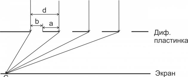
| Exercise | A monochromatic beam of light with a wavelength of . There is a screen at a distance L from the grating, on which a spectral diffraction pattern is formed using a lens. It is found that the first main diffraction maximum is located at a distance x from the central one (Fig. 1). What is the diffraction grating constant (d)? |
| Solution | Let's make a drawing. |
1. Diffraction of light. Huygens-Fresnel principle.
2. Diffraction of light by slits in parallel rays.
3. Diffraction grating.
4. Diffraction spectrum.
5. Characteristics of a diffraction grating as a spectral device.
6. X-ray structural analysis.
7. Diffraction of light by a round hole. Aperture resolution.
8. Basic concepts and formulas.
9. Tasks.
In a narrow, but most commonly used sense, light diffraction is the bending of light rays around the boundaries of opaque bodies, the penetration of light into the region of a geometric shadow. In phenomena associated with diffraction, there is a significant deviation in the behavior of light from the laws of geometric optics. (Diffraction is not limited to light.)
Diffraction is a wave phenomenon that manifests itself most clearly in the case when the dimensions of the obstacle are commensurate (of the same order) with the wavelength of light. The rather late discovery of light diffraction (16th-17th centuries) is associated with the small lengths of visible light.
21.1. Diffraction of light. Huygens-Fresnel principle
Diffraction of light is a complex of phenomena that are caused by its wave nature and are observed during the propagation of light in a medium with sharp inhomogeneities.
A qualitative explanation of diffraction is given by Huygens principle, which establishes the method for constructing the wave front at time t + Δt if its position at time t is known.
1.According to Huygens' principle each point on the wave front is the center of coherent secondary waves. The envelope of these waves gives the position of the wave front at the next moment in time.
Let us explain the application of Huygens' principle using the following example. Let a plane wave fall on an obstacle with a hole, the front of which is parallel to the obstacle (Fig. 21.1).
Rice. 21.1. Explanation of Huygens' principle
Each point of the wave front isolated by the hole serves as the center of secondary spherical waves. The figure shows that the envelope of these waves penetrates the region of the geometric shadow, the boundaries of which are marked with a dashed line.
Huygens' principle says nothing about the intensity of secondary waves. This drawback was eliminated by Fresnel, who supplemented Huygens' principle with the idea of the interference of secondary waves and their amplitudes. The Huygens principle supplemented in this way is called the Huygens-Fresnel principle.
2. According to Huygens-Fresnel principle the magnitude of light vibrations at a certain point O is the result of the interference at this point of coherent secondary waves emitted everyone elements of the wave surface. The amplitude of each secondary wave is proportional to the area of the element dS, inversely proportional to the distance r to point O and decreases with increasing angle α between normal n to element dS and direction to point O (Fig. 21.2).
 Rice. 21.2. Emission of secondary waves by wave surface elements
21.2. Slit diffraction in parallel beams
Calculations associated with the application of the Huygens-Fresnel principle are, in general, a complex mathematical problem. However, in a number of cases with a high degree of symmetry, the amplitude of the resulting oscillations can be found by algebraic or geometric summation. Let us demonstrate this by calculating the diffraction of light by a slit.
Let a flat monochromatic light wave fall on a narrow slit (AB) in an opaque barrier, the direction of propagation of which is perpendicular to the surface of the slit (Fig. 21.3, a). We place a collecting lens behind the slit (parallel to its plane), in focal plane which we will place the screen E. All secondary waves emitted from the surface of the slit in the direction parallel optical axis of the lens (α = 0), the lens comes into focus in the same phase. Therefore, at the center of the screen (O) there is maximum interference for waves of any length. It's called the maximum zero order.
In order to find out the nature of the interference of secondary waves emitted in other directions, we divide the slit surface into n identical zones (they are called Fresnel zones) and consider the direction for which the condition is satisfied:
where b is the slot width, and λ - light wavelength.
Rays of secondary light waves traveling in this direction will intersect at point O."
 Rice. 21.3. Diffraction at one slit: a - ray path; b - distribution of light intensity (f - focal length of the lens)
The product bsina is equal to the path difference (δ) between the rays coming from the edges of the slit. Then the difference in the path of the rays coming from neighboring Fresnel zones is equal to λ/2 (see formula 21.1). Such rays cancel each other out during interference, since they have the same amplitudes and opposite phases. Let's consider two cases.
1) n = 2k is an even number. In this case, pairwise suppression of rays from all Fresnel zones occurs and at point O" a minimum of the interference pattern is observed.
Minimum intensity during diffraction by a slit is observed for the directions of rays of secondary waves satisfying the condition
The integer k is called on the order of the minimum.
2) n = 2k - 1 - odd number. In this case, the radiation of one Fresnel zone will remain unquenched and at point O" the maximum interference pattern will be observed.
The maximum intensity during diffraction by a slit is observed for the directions of rays of secondary waves satisfying the condition:
The integer k is called order of maximum. Recall that for the direction α = 0 we have maximum of zero order.
From formula (21.3) it follows that as the light wavelength increases, the angle at which a maximum of order k > 0 is observed increases. This means that for the same k, the purple stripe is closest to the center of the screen, and the red stripe is furthest away.
In Figure 21.3, b shows the distribution of light intensity on the screen depending on the distance to its center. The main part of the light energy is concentrated in the central maximum. As the order of the maximum increases, its intensity quickly decreases. Calculations show that I 0:I 1:I 2 = 1:0.047:0.017.
If the slit is illuminated by white light, then the central maximum on the screen will be white (it is common to all wavelengths). Side highs will consist of colored bands.
A phenomenon similar to slit diffraction can be observed on a razor blade.
21.3. Diffraction grating
In slit diffraction, the intensities of maxima of order k > 0 are so insignificant that they cannot be used to solve practical problems. Therefore, it is used as a spectral device diffraction grating, which is a system of parallel, equally spaced slits. A diffraction grating can be obtained by applying opaque streaks (scratches) to a plane-parallel glass plate (Fig. 21.4). The space between the strokes (slots) allows light to pass through.
The strokes are applied to the surface of the grating with a diamond cutter. Their density reaches 2000 lines per millimeter. In this case, the width of the grille can be up to 300 mm. The total number of grating slits is denoted N.
The distance d between the centers or edges of adjacent slits is called constant (period) diffraction grating.
The diffraction pattern on a grating is determined as the result of mutual interference of waves coming from all slits.
The path of rays in a diffraction grating is shown in Fig. 21.5.
Let a plane monochromatic light wave fall on the grating, the direction of propagation of which is perpendicular to the plane of the grating. Then the surfaces of the slots belong to the same wave surface and are sources of coherent secondary waves. Let us consider secondary waves whose direction of propagation satisfies the condition
After passing through the lens, the rays of these waves will intersect at point O."
The product dsina is equal to the path difference (δ) between the rays coming from the edges of adjacent slits. When condition (21.4) is satisfied, secondary waves arrive at point O" in the same phase and a maximum interference pattern appears on the screen. Maxima that satisfy condition (21.4) are called main maxima of order k. Condition (21.4) itself is called the basic formula of a diffraction grating.
Major Highs during diffraction by a grating are observed for the directions of rays of secondary waves satisfying the condition: dsinα = ± κ λ; k = 0,1,2,...
 Rice. 21.4. Cross section of a diffraction grating (a) and its symbol (b)
 Rice. 21.5. Diffraction of light by a diffraction grating
For a number of reasons that are not discussed here, between the main maxima there are (N - 2) additional maxima. With a large number of slits, their intensity is negligible and the entire space between the main maxima appears dark.
Condition (21.4), which determines the positions of all main maxima, does not take into account diffraction at a separate slit. It may happen that for some direction the condition will be simultaneously satisfied maximum for the lattice (21.4) and the condition minimum for the slot (21.2). In this case, the corresponding main maximum does not arise (formally it exists, but its intensity is zero).
The greater the number of slits in the diffraction grating (N), the more light energy passes through the grating, the more intense and sharper the maxima will be. Figure 21.6 shows intensity distribution graphs obtained from gratings with different numbers of slits (N). The periods (d) and slot widths (b) are the same for all gratings.
 Rice. 21.6. Intensity distribution at different values of N
21.4. Diffraction spectrum
From the basic formula of a diffraction grating (21.4) it is clear that the diffraction angle α, at which the main maxima are formed, depends on the wavelength of the incident light. Therefore, intensity maxima corresponding to different wavelengths are obtained in different places on the screen. This allows the grating to be used as a spectral device.
Diffraction spectrum- spectrum obtained using a diffraction grating.
When white light falls on a diffraction grating, all maxima except the central one will be decomposed into a spectrum. The position of the maximum of order k for light with wavelength λ is determined by the formula:
The longer the wavelength (λ), the farther the kth maximum is from the center. Therefore, the violet region of each main maximum will face the center of the diffraction pattern, and the red region will face outward. Note that when white light is decomposed by a prism, violet rays are more strongly deflected.
When writing the basic lattice formula (21.4), we indicated that k is an integer. How big can it be? The answer to this question is given by the inequality |sinα|< 1. Из формулы (21.5) найдем
where L is the width of the grating, and N is the number of lines.
For example, for a grating with a density of 500 lines per mm d = 1/500 mm = 2x10 -6 m. For green light with λ = 520 nm = 520x10 -9 m we get k< 2х10 -6 /(520 х10 -9) < 3,8. Таким образом, для такой решетки (весьма средней) порядок наблюдаемого максимума не превышает 3.
21.5. Characteristics of a diffraction grating as a spectral device
The basic formula of a diffraction grating (21.4) allows you to determine the wavelength of light by measuring the angle α corresponding to the position of the kth maximum. Thus, a diffraction grating makes it possible to obtain and analyze spectra of complex light.
Spectral characteristics of the grating
Angular dispersion - a value equal to the ratio of the change in the angle at which the diffraction maximum is observed to the change in wavelength:
 where k is the order of maximum, α -
the angle at which it is observed.
where k is the order of maximum, α -
the angle at which it is observed.
The higher the order k of the spectrum and the smaller the grating period (d), the higher the angular dispersion.
Resolution(resolving power) of a diffraction grating - a quantity characterizing its ability to produce
 where k is the order of the maximum, and N is the number of grating lines.
It is clear from the formula that close lines that merge in a first-order spectrum can be perceived separately in second- or third-order spectra.
21.6. X-ray diffraction analysis
The basic diffraction grating formula can be used not only to determine the wavelength, but also to solve the inverse problem - finding the diffraction grating constant from a known wavelength.
The structural lattice of a crystal can be taken as a diffraction grating. If a stream of X-rays is directed onto a simple crystal lattice at a certain angle θ (Fig. 21.7), then they will diffract, since the distance between the scattering centers (atoms) in the crystal corresponds to
x-ray wavelength. If a photographic plate is placed at some distance from the crystal, it will register the interference of reflected rays.
 where d is the interplanar distance in the crystal, θ is the angle between the plane
 Rice. 21.7. X-ray diffraction by a simple crystal lattice; the dots indicate the arrangement of atoms
crystal and the incident X-ray beam (grazing angle), λ is the wavelength of the X-ray radiation. Relationship (21.11) is called Bragg-Wolfe condition.
If the wavelength of X-ray radiation is known and the angle θ corresponding to condition (21.11) is measured, then the interplanar (interatomic) distance d can be determined. X-ray diffraction analysis is based on this.
X-ray structural analysis - a method for determining the structure of a substance by studying the patterns of X-ray diffraction on the samples being studied.
X-ray diffraction patterns are very complex because the crystal is a three-dimensional object and the X-rays can diffract on different planes at different angles. If the substance is a single crystal, then the diffraction pattern is an alternation of dark (exposed) and light (unexposed) spots (Fig. 21.8, a).
In the case when the substance is a mixture of a large number of very small crystals (as in a metal or powder), a series of rings appears (Fig. 21.8, b). Each ring corresponds to a diffraction maximum of a certain order k, and the x-ray pattern is formed in the form of circles (Fig. 21.8, b).
 Rice. 21.8. X-ray pattern for a single crystal (a), X-ray pattern for a polycrystal (b)
X-ray diffraction analysis is also used to study the structures of biological systems. For example, the structure of DNA was established using this method.
21.7. Diffraction of light by a circular hole. Aperture resolution
In conclusion, let us consider the issue of light diffraction by a round hole, which is of great practical interest. Such openings are, for example, the pupil of the eye and the lens of a microscope. Let light from a point source fall on the lens. A lens is an opening that allows only Part light wave. Due to diffraction on the screen located behind the lens, a diffraction pattern will appear as shown in Fig. 21.9, a.
As for the gap, the intensities of the side maxima are low. The central maximum in the form of a light circle (diffraction spot) is the image of a luminous point.
The diameter of the diffraction spot is determined by the formula:
where f is the focal length of the lens and d is its diameter.
If light from two point sources falls on a hole (diaphragm), then depending on the angular distance between them (β) their diffraction spots can be perceived separately (Fig. 21.9, b) or merge (Fig. 21.9, c).
Let us present without derivation a formula that provides a separate image of close point sources on the screen (aperture resolution):
where λ is the wavelength of the incident light, d is the diameter of the hole (diaphragm), β is the angular distance between the sources.
 Rice. 21.9. Diffraction at a circular hole from two point sources
21.8. Basic concepts and formulas
 End of the table
 21.9. Tasks
1. The wavelength of light incident on the slit perpendicular to its plane is 6 times the width of the slit. At what angle will the 3rd diffraction minimum be visible?
2. Determine the period of a grating with width L = 2.5 cm and having N = 12500 lines. Write your answer in micrometers.
Solution
d = L/N = 25,000 µm/12,500 = 2 µm. Answer: d = 2 µm.
3. What is the constant of the diffraction grating if in the 2nd order spectrum the red line (700 nm) is visible at an angle of 30°?
4. The diffraction grating contains N = 600 lines at L = 1 mm. Find the highest spectral order for light with wavelength λ = 600 nm.
5. Orange light with a wavelength of 600 nm and green light with a wavelength of 540 nm pass through a diffraction grating having 4000 lines per centimeter. What is the angular distance between the orange and green maxima: a) first order; b) third order?
 Δα = α or - α z = 13.88° - 12.47° = 1.41°.
 6.
Find the highest order of the spectrum for the yellow sodium line λ = 589 nm if the lattice constant is d = 2 µm.
6.
Find the highest order of the spectrum for the yellow sodium line λ = 589 nm if the lattice constant is d = 2 µm.
Solution
Let us reduce d and λ to the same units: d = 2 µm = 2000 nm. Using formula (21.6) we find k< d/λ = 2000/ 589 = 3,4. Answer: k = 3.
7. A diffraction grating with a number of slits N = 10,000 is used to study the light spectrum in the region of 600 nm. Find the minimum wavelength difference that can be detected by such a grating when observing second-order maxima.
- In contact with 0
- Google+ 0
- OK 0
- Facebook 0