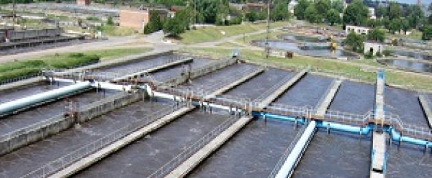
Bioponds are created artificially near the enterprises of the petrochemical, coke-chemical, oil-producing industries, and in places of pulp production. These are buried treatment reservoirs, protected by a dam or dam.
Biological ponds with polluted waste water from the enterprise are built in places unsuitable for management Agriculture. As a rule, these are ravines, slopes of terraces. Each sewage treatment plant is protected by a dam for safety purposes, and if it is located in a deep ravine, by a dam.
Settling ponds are the cause of wastewater pollution, biologists are fighting the flowering of these reservoirs. The water is chemically clarified. In ponds, natural processes of self-purification and aeration of wastewater take place.
Waste water storage conditions
A biological pond should store only the effluents of those waters that do not change their qualities throughout the entire period of storage. It is still necessary to monitor the absence of pollution of the reservoir with silt. The waste storage pond should function in a temporary, not permanent manner.
It is emphasized that there are no special requirements for the construction of a treatment pond. A reservoir of up to 50,000 m3 fills underground clean channels at a distance of several square kilometers.
It should be noted that, according to the estimates of LISI specialists, at present a treatment pond is being built with a volume of up to 40,000 m3. Each biological settling pond is very polluting the air, releasing active chemicals into it.
The principle of constructing a sewage pond
Pond construction technology
According to technological requirements, the storage pond should consist of 2 parts. The first occupies 20% of the volume of the entire pond and serves to filter and settling particles of oil products. The second part, with a volume of 80%, functions as a kind of battery.
It should be noted that a swampy lake or swamp can be used as a storage pond if there is a sewage drain and a large area of land nearby.
The method of using a biological swamp lake is economically viable, but the sewage sediments become thixotropic in the swamp, the pond is covered with a hard crust, lime does not help to eliminate the problem, so the storage pond should be a temporary option.
The pond-station is built taking into account the water level in a nearby natural reservoir during the flood period. The data is taken from the last 10 years. An arid (desert) zone for the construction of ponds to collect wastewater in the cold season can significantly increase soil fertility and productivity if a well-thought-out drainage system is installed.
Type of wastewater treatment plant
The type of treatment plant is determined depending on the nature of the sludge in the wastewater. Biological accumulators are divided into single-phase and two-phase. Industrial sludge with a pronounced color and strong odor, containing salts that cannot be processed, is sent to single-phase storage tanks, and sludge in the form of an aqueous suspension containing minerals and organic substances that can be separated is sent to two-phase storage tanks.
Hydraulic dumps - custodians of wastewater
Hydraulic dumps are structures - stations designed for storing pulp. Pulp is a finely divided suspension of water and rock. The pulp is in the form:
- coarse suspension;
- fine suspension;
- silt (sludge);
- colloid solution.
According to the type of bottom topography, biological hydraulic dumps-ponds are divided into:
- specially erected and fenced with a dam or dam;
- located in the floodplain of the river, bunded from 3-4 sides;
- low-lying, flat ponds;
- career bioponds;
- erected in places of natural deepening of the relief;
- pit and basin ponds.
Characteristics of hydro dumps 
Hydraulic dumps in height are low, up to 12 meters, medium, from 12 to 35 meters, high, from 35 meters and above. The station structure should contain a bunded dam, water collection devices and drainage systems. small volume surface water on the territory of a biological hydrodump, they are collected by a catchment plant, and large flood waters are collected using a special culvert mechanism.
The silt pad is built in a natural place of lowering the relief or is built artificially. The station is designed to evaporate water from sediments and remove the necessary residues to be processed. It is a recess, flanked by a dam from 2 to 3 sides with roads for the possibility of access for transport and vehicles in order to remove the remains of dumps by workers, review and pack for further transportation.
Silt area for the accumulation of wastewater
A biological sludge site-station is built from several sludge maps with valves, drain pipes, and drainage for sewage systems. Silt pads are arranged in a row with each other at a certain angle of inclination, which corresponds to the technical operation of each pad. One-time sewage coverage of all maps is unacceptable. The maps are covered with water and waste in a certain order: 25-35 cm in summer and 15 cm in winter below the upper level of the dam.
Pipes, valves, trays are inspected by employees at least once every 5 days. Useful residues are removed from the cards after the wastewater has completely drained into the pit and passed into the drainage system, and the residues have dried. Water from the pit is removed through the operation of water treatment plants. Platform spreading devices and their channels are washed with clean water after each application of precipitation. V winter period the sliding open tray is covered with several water shields.
Feature of the tailing dump and reservoir - evaporator
The tailings pond is a reservoir of liquid industrial effluents and waters containing minerals (tailings) suitable for recycling using biological enrichment technology. As needed, secondary dams are built in addition to the main one. The water in the reservoir is clarified. Dams against waters are built in bulk.
The evaporation pond is based on an embankment dam and a natural relief depression. An impervious film of moisture-proof material is laid at the base of the pond, which is buried to the level of clay underground. Evaporation ponds differ among themselves depending on the geological, climatic, terrain conditions and wastewater. By type of relief there are:
- ravine ponds;
- floodplain ponds;
- flat;
- pits.
Construction of a sludge storage
The sludge storage is a huge earthen pond up to tens of thousands of m3, lined with a dam with a protective ridge, equipped with a catchment and drainage system. The comb must be equipped with a system of ditches for the supply and removal of water.
This system is arranged according to the principle of operation similar to the one in the tailings. The sludge storage is designed for screening and recycling of oil industry waste. Water runoff is a suspension of suspended oil particles.
Technology for the construction of treatment ponds
Special attention is paid to the technology of construction of treatment water bodies in accordance with the norms
mothers and environmental laws in force in the Russian Federation.
All hydraulic structures must be built according to projects developed in a certain order and passed an examination in accordance with the Decree of the State Duma of the Russian Federation of December 7, 2000:
- The owner of the hydraulic structure, before starting construction, must submit to the Gosgortekhnadzor a project for the construction of a treatment plant that meets the regulatory requirements.
- The owner of the hydraulic structure is fully responsible for:
- the pond itself
- communication,
- approaches and entrances to the hydraulic structure,
- supplied drainage system,
- water collection and water intake systems for water drainage,
- quality of water discharged into open water.
- The owner of a hydraulic structure must submit an accident response plan to the supervisory authority after:
- elimination of the storage reservoir,
- problems with the drainage system,
- spillage of polluted waters over the territory adjacent to the pond.
- The regulatory law provides for the monitoring of a hydraulic structure in order to prevent a possible accident and determine the level of pollution of the surrounding area.
- The management of the hydraulic structure is obliged to develop for the supervisory authority a plan for the operation of the treatment plant, instructions for the local use of the pond, safety instructions, service instructions for all working personnel.
- The management of small and medium-sized storage facilities can develop and approve an accident elimination plan as part of an accident localization plan for the entire service enterprise or its subdivision.
If there are residential premises or objects of science, education, medicine in the toxic water spill zone planned by the technical project, they must be immediately transferred from the specified zone.
Causes and conditions for the liquidation of a reservoir 
The accumulator, after filling it up to the upper working mark, is subject to conservation (liquidation). For this purpose, it is necessary to obtain an expert opinion from Gosgortekhnadzor on the state of the repository and its impact on the environment, as well as develop a plan for the elimination of the treatment plant itself in accordance with the expert opinion. The accumulator is liquidated in the event of:
- its location in a residential area;
- overflowing with toxic waste, when impervious films and products do not contain them, and polluted water seeps into the ground, poisoning clean sources.
The project for the liquidation of a hydraulic structure must be carried out by an organization that has a license for its construction. The project must provide for requirements for maintaining safety environment and industrial enterprise. The safety of the conservation of the object is ensured by the owner or the organization using the hydraulic structure in accordance with the conclusion expert commission and specialists from Rostekhnadzor.
One of the most pressing environmental problems today is the treatment of a variety of wastewater contaminated with various ecotoxicants. There are a number of ways to solve this problem, one of which is the development and implementation of biological methods for the treatment and post-treatment of wastewater. These methods are based on the practically unlimited ability of living organisms to use the variety of substances contained in wastewater in their life processes.
Biological treatment is applied to effluents, which are mainly polluted with organic substances and biogenic elements, and are also characterized by a high content of suspended solids. biological methods have proven themselves in the system of municipal wastewater treatment, as the most environmentally and economically beneficial. They are used for wastewater treatment of enterprises in the dairy, canning, food, oil refining industries, in animal husbandry, etc.
Aerobic cleaning Wastewater
Biological waste processing is based on a number of disciplines: biochemistry, genetics, chemistry, microbiology, computer technology. The efforts of these disciplines are concentrated on three main areas:
- degradation of organic and inorganic toxic waste;
- Renewal of resources for returning carbon, nitrogen, phosphorus, nitrogen and sulfur to the cycle of substances;
- obtaining valuable types of organic fuel.
There are four main steps in wastewater treatment:
1. During primary processing, wastewater is averaged and clarified from mechanical impurities (averagers, sand traps, grates, settling tanks).
2. At the second stage, the destruction of dissolved organic matter with the participation of aerobic microorganisms. The resulting sludge, which consists mainly of microbial cells, is either removed or pumped into the reactor. With technology using activated sludge, part of it is returned to the aeration tank.
3. At the third (optional) stage, chemical precipitation and separation of nitrogen and phosphorus are performed.
4. The sludge generated in the first and second stages is usually treated with an anaerobic decomposition process. At the same time, the volume of sediment and the number of pathogens are reduced, odor is eliminated, and valuable organic fuel, methane, is formed.
In practice, single-stage and multi-stage cleaning systems are used. A single-stage wastewater treatment scheme is shown in the figure:
Schematic diagram of treatment facilities:
1 - sand traps; 2 - primary settling tanks; 3 - aeration tank; 4 - secondary settling tanks; 5 - biological ponds; 6 - clarification; 7 - reagent treatment; 8 - metatank; AI - activated sludge.
Wastewater enters the equalizer, where there is an intensive mixing of wastewater with different qualitative and quantitative composition. Mixing is carried out by air supply. If necessary, biogenic elements in the required quantities and ammonia water are also fed into the equalizer to create a certain pH value. The residence time in the homogenizer is usually several hours. When cleaning fecal effluents and oil refining waste, a necessary element of treatment facilities is a mechanical treatment system - sand traps and primary settling tanks. They separate the treated water from coarse suspensions and oil products that form a film on the surface of the water.
Biological water treatment takes place in aeration tanks. The aerotank is an open reinforced concrete structure through which wastewater passes, containing organic pollutants and activated sludge. Suspension of sludge in wastewater throughout the time spent in the aeration tank is subjected to air aeration. Intensive aeration of activated sludge suspension with oxygen restores its ability to absorb organic impurities.
Biological water treatment is based on the activity of activated sludge (AI) or biofilm, a naturally occurring biocenosis that is formed in each specific production, depending on the composition of wastewater and the selected treatment mode. Activated sludge is a dark brown flake, up to several hundred micrometers in size. It consists of 70% living organisms and 30% solid particles of inorganic nature. Living organisms, together with a solid carrier, form a zoogle - a symbiosis of populations of microorganisms, covered with a common mucous membrane. Microorganisms isolated from activated sludge belong to various genera: Actynomyces, Azotobacter, Bacillus, Bacterium, Corynebacterium, Desulfomonas, Pseudomonas, Sarcina, etc. The most numerous bacteria of the Pseudomonas genus, the omnivorous nature of which was mentioned earlier. Depending on the external environment, which in this case is wastewater, one or another group of bacteria may be predominant, and the rest become satellites of the main group.
Anaerobic treatment systems
As already mentioned, excess activated sludge can be recycled in two ways: after drying as a fertilizer, or it enters the anaerobic treatment system. The same purification methods are also used for the fermentation of highly concentrated effluents containing a large amount of organic matter. Fermentation processes are carried out in special devices - metatanks.
The decomposition of organic matter consists of three stages:
- dissolution and hydrolysis of organic compounds;
- acidogenesis;
- methanogenesis.
At the first stage, complex organic substances are converted into butyric, propionic and lactic acids. In the second step, these organic acids are converted into acetic acid, hydrogen, carbon dioxide. In the third step, methane-producing bacteria reduce carbon dioxide to methane with hydrogen uptake. In terms of species composition, the biocenosis of metatenks is much poorer than aerobic biocenoses.
There are about 50 types of microorganisms capable of carrying out the first stage - the stage of acid formation. The most numerous among them are representatives of bacilli and pseudomonads. Methane-producing bacteria have a variety of shapes: cocci, sarcins, and rods. The stages of anaerobic fermentation proceed simultaneously, while the processes of acid formation and methane formation proceed in parallel. Acetic acid and methane-producing microorganisms form a symbiosis, previously considered to be one microorganism called Methanobacillus omelianskii.
The process of methane formation is a source of energy for these bacteria, since methane fermentation is one of the types of anaerobic respiration, during which electrons from organic substances are transferred to carbon dioxide, which is reduced to methane. As a result of the vital activity of the biocenosis of the metatank, the concentration of organic substances decreases and the formation of biogas, which is an environmentally friendly fuel. Biogas can be obtained from agricultural waste, effluents from processing plants containing sugar, household waste, wastewater from cities, distilleries, etc.
The metatank is a hermetic fermenter with a volume of several cubic meters with stirring, which is necessarily equipped with gas separators with flame traps. Metatanks operate in a batch loading mode of waste or waste water with a constant selection of biogas and unloading of solid sludge after the completion of the process. In general, the active use of methanogenesis in the digestion of organic waste is one of the promising ways to jointly solve energy and environmental issues, which allows agro-industrial complexes to switch to autonomous energy supply.
Biotreatment serves as the final stage after mechanical and physico-chemical treatment, after which water of the appropriate quality is released into natural reservoirs or onto a relief.
Biological ponds, being the final link in the processes of biological wastewater treatment, finally form the quality of water discharged into water bodies. The presence of bioponds in the system of treatment facilities makes it possible to significantly smooth out negative influence poorly treated effluents to water basins.
Particular attention should be paid to the availability and efficient operation of biological ponds where treatment facilities work unsatisfactorily. First of all, this applies to those enterprises where biological ponds are practically the only active element in the treatment system.
On the this moment in the practice of cleaning household and industrial wastewater, most biological ponds have been transferred to a non-drainage mode. Thus, the surface discharge of water into natural reservoirs has almost completely stopped. This had a positive effect on the ecological state of medium and small water basins, significantly slowing down their eutrophication.
K category: Sewage treatment
Biological wastewater treatment in natural conditions
Biological wastewater treatment in natural conditions can be carried out in biological ponds, in filtration fields and underground filtration facilities, as well as in agricultural irrigation fields.
Biological ponds are artificially created shallow water bodies in which biological wastewater treatment takes place on weakly filtering soils, based on the processes that occur during the self-purification of water bodies. Biological ponds can also be used for post-treatment of wastewater after it has passed through other biological treatment facilities. Ponds are single (shallow stagnant 0.6-1.2 m deep) or consisting of three to five ponds, through which the clarified or biologically purified waste liquid slowly flows.
Biological ponds can be used for wastewater treatment in the IV climatic region all year round, in the II and III climatic regions - only in the warm season, and in the cold season, provided that the water in the bioponds has a temperature of at least 8 ° C.
Wastewater treatment in biological ponds can take place under anaerobic and aerobic conditions. Anaerobic ponds have a depth of 2.5-3 m, the BOD load for domestic wastewater is 300-350 kg/ /(ha-day). Aerobic bioponds with natural aeration can be used for wastewater treatment with BOD.5 concentration not higher than 200-250 mg/l in climatic zone IV year-round, and in climatic zones II and III - only during the warm period. The estimated load on the ponds for settled wastewater is taken up to 250 m3/(ha-day), for biologically treated water - up to 5000 m3/(ha-day). With a pond area of 0.5-0.25 ha, the residence time of wastewater, depending on the load, ranges from 2.5 to 10 days.
It is expedient to carry out bnoponds for complete cleaning in two or three stages, taking in each of the stages the degree of purification according to BOD.5 equal to 70%. To intensify the process of wastewater treatment, oxygen from the air is artificially supplied to the bioponds. Such bioponds occupy a much smaller area and are less dependent on climatic conditions; they can operate at air temperatures from -15 to -20 °C, and on some days even up to -45 °C.
Research VNII VODGEO, MISI them. V. V. Kuibyshev and TsNIIEP of engineering equipment, as well as the results of production tests of the Belarusian Research Sanitary and Hygienic Institute, confirmed the feasibility of using aerated bioponds for wastewater treatment in rural areas with a capacity of 100-10,000 m3 / day, and for post-treatment - up to 50,000 m3/day
Aerated bioponds can be used for wastewater treatment with BOD5 concentration up to 500 mg/l, they provide efficient wastewater treatment in II and III climatic zones. In northern regions II climate zone, as well as in areas with stable winds in winter time years, it is more expedient to use biological ponds with a recirculation cycle (return) of the sludge mixture, which have better thermal characteristics. Before bioponds, mechanical wastewater treatment should be provided. At a concentration of suspended solids up to 250 mg/l, the settling time can be taken equal to 0.5 h, at a concentration of 250-500 mg/l-1 h.
Rice. 1. Plan of the station for biological wastewater treatment with a capacity of 700 m3 / day 1, 2, 3, 4 - aerated ponds, respectively, I, II, III, IV stages: 5 - settling pond; 6 - contact pond; 7 - industrial building: 8 - suction pipeline of industrial water; 9 - air duct; 10 - industrial water pressure pipeline; 11 - receiving chamber; 12 - supply pipeline with a diameter of 300 mm; 13 - two-tier sump; 14, 17 - sand platforms; 15 - sand pipeline; 16 - silt pads
The construction of treatment facilities with aerated bioponds requires the least capital investment compared to treatment by other methods. Unit costs at these stations are 20-50% lower. In addition, aerated bioponds are characterized high level mechanization of earthworks and minimal consumption of reinforced concrete and other building materials.
Filtration fields can be applied in some cases in the presence of unsuitable for agricultural use land plots with filtering soils, in the absence of the risk of contamination of groundwater used for drinking purposes. Land plots of filtration fields are specially prepared for biological wastewater treatment, preventing their use for agricultural purposes. Sewage supplied to the fields enters individual sections (maps) through a system of open trays or channels (divided channels); the complex of these canals makes up the irrigation network. The collection and removal of filtered purified water is carried out using drainage, which can be open in the form of ditches along the perimeter of the maps or closed, consisting of drainage pipes laid along the map at a depth of 1.5-2 m, and ditches. A system of drainage and ditches forms a drainage system. Channels are made of brick, buta, reinforced concrete, concrete or made of earth. The channels have a rectangular or trapezoidal cross section; they are placed along the enclosing earthen rolls.
When designing filtration fields, open areas not flooded by spring waters are selected with a calm terrain with a natural slope of not more than 0.02. For the arrangement of filtration fields, areas located close to the places of wedging out of aquifers, as well as peat and clay soils and solonchaks, are not suitable. The most suitable sandy and sandy soils. Fields are recommended to be located on the leeward side at a certain distance from residential areas, depending on the flow of wastewater: at a flow rate of up to 5000 m3 / day, this distance is taken as 300 m, at 5000-50,000 m3 / day - 500 m and more than 50,000 m3 / day -1000 m. Willow and other moisture-loving plantings are usually planted along the contour of the fields. The width of the planting strip is 10-20 m, depending on the distance of the fields from settlements.
Domestic wastewater treated at filtration fields has a BOD of 10-15 mg/l, 99% stability (ie does not rot), contains nitrates up to 25 mg/l. The number of bacteria is reduced by 99-99.9% compared to their content in the source water. Special disinfection is not required. For the successful operation of the fields, it is necessary to supply them with waste water, previously clarified, i.e. largely free of suspended particles. In addition, when settling from the waste liquid, up to 50--80% of helminths are precipitated, which reduces soil pollution by 7-10 times.
The required area for filtration fields is determined based on the load rate - the allowable amount of wastewater that can be treated per 1 ha of the field surface. In addition, the nature of the soil, the level of groundwater and the average annual temperature according to the load standards are taken into account. Load rates of clarified wastewater on filtration fields for areas with an average annual rainfall of 300-500 mm are given in SNiP 2.04.03-85.
It is necessary to provide additional area for the construction of map fences, irrigation network, roads and entrances to maps. So, with a usable area of filtration fields up to 0.3 ha, the additional area is provided equal to 100% of the usable area, with 0.5 ha - 90, with 0.8-80, with 1 ha - 60 and more than 1 ha - 40% of the usable area fields.
When arranging filtration fields, permanent and temporary irrigation networks are usually provided. The permanent irrigation network (Fig. 2) consists of a main canal, group distribution canals and kart sprinklers serving individual karts. Kartovyn sprinkler - the last element of the permanent network.

Rice. 2. Scheme of irrigation fields 1 - main and distribution canals; 2 - sled sprinklers; 3 - drainage ditches; 4 - drainage; 5 - roads
The irrigation network is designed from ceramic or asbestos-cement pipes with a diameter of 75-100 mm. It is allowed to use irrigation trays made of brick, concrete and other materials. Irrigation pipes are laid in sandy soils with a slope of 0.001-0.003, and in sandy loamy soils - horizontally. The distance between parallel irrigation pipes in sands is 1.5-2.0 m, in sandy loam - 2.5 m. Ceramic pipes are laid with gaps of 15-20 mm; linings should be provided above the pipe joints. In asbestos-cement pipes of irrigation networks, half-diameter cuts 15 mm wide are made from below. The distance between the cuts should be no more than 2 m. For air inflow, risers with a diameter of 100 mm are installed at the ends of the irrigation pipes, rising 0.5 m above the ground.

Rice. Fig. 3. Scheme of arrangement of underground filtration fields 1 - outlet from the building; 2 - a three-chamber septic tank made of reinforced concrete rings; 3 - dosing chamber with dosing siphon; 4 - distribution chamber; 5 - drains
The drainage network in the filtration fields is provided for under adverse soil conditions. It consists of a drainage, a combined network, outlet lines and outlets. The drainage system is integral part fields, as it allows timely removal of excess soil moisture and contributes to the penetration of air into the active layer, without which the aerobic oxidative process cannot take place. In impermeable soils (loams), closed drainage is constructed, in permeable soils (sands, sandy loams), drainage is either not required at all, or open drainage ditches are arranged.
The distance between the drains depends on the degree of water permeability of the soil, the depth of the drained layer, the depth of the drains, the amount of water drained, etc. For preliminary calculations, the distance between the drains in sands is 16-25 m, in sandy loams 12-15 m and in light loams 8-10 m. In coarse-grained sands, in some cases, drainage is constructed in the form of open drainage ditches with a distance of up to 100 m between them.
Closed drainage is arranged mainly from unglazed pottery pipes with a diameter of 75-100 mm.
Drains should be located perpendicular to the direction of groundwater flow with a slope of 0.0025-0.005. Between the pipes leave gaps of 4-5 mm. A clay pillow is laid under the joints, the joints are covered with roofing felt or felt from above. Open drainage ditches, prefabricated networks and outlets are arranged in the form of trapezoidal channels with side walls at an angle of natural repose of soils.
In winter, after the freezing of the soil, the filtration of sewage in the fields of filtration slows down significantly, and sometimes stops completely, and the sewage discharged onto the fields freezes. Therefore, in areas with a cold and temperate climate, the filtration fields should be checked for frost. Usually, the height of the freezing layer of wastewater is 0.6-0.8 m, in accordance with which the height of the shafts enclosing the card is determined.
Underground filtration facilities. Underground filtration fields are used to treat small amounts of wastewater. Waste water from a building or a group of buildings is directed to a septic tank for preliminary clarification (Fig. 3). Clarified water enters a network of pipelines laid at a depth of 0.3-1.2 m with unsealed joints, through which wastewater penetrates into the ground, where it is further cleaned. The treated waste water is not collected in the drainage network, but seeps into the soil or partially leaves with the ground flow.
Growing garden crops is allowed on the territory of underground filtration fields. The disadvantage of filtration fields is the need for a wide sanitary break zone (200-300 m). For facilities with a wastewater flow rate of up to 12 m3 / day, in some cases (if there are filtering soils, deep groundwater and there is no danger of pollution of aquifers used for drinking water supply), treatment facilities operating on the principle of underground wastewater filtration can be adopted ( sand and gravel filters, filter trenches, filter wells). These structures are quite simple in construction and operation and are intended for complete biological treatment.
Underground filtration facilities (unlike surface filtration fields) can be located near the buildings they serve and do not require the construction of an external sewer network of considerable length. Waste water flows to the treatment plant by gravity, and therefore no pumping stations are required. It is advisable to arrange such structures in sandy, sandy and light loamy soils.
Waste water from a building or group of buildings is sent for preliminary clarification to a septic tank. Clarified water through the dosing chamber and the distribution well enters the drainage pipes located at least 1 m above the groundwater level, or the filter well. Through unsealed joints and cuts in pipes or holes in the walls of the well, the clarified liquid enters the ground, where it is further cleaned. Underground filtration systems eliminate air pollution and upper layers soil.
Standard projects of treatment facilities for underground filtration systems are developed in accordance with a unified range of such facilities of low productivity 0.5-12 m3/day. The range of standard projects includes: septic tanks; systems with underground filtration fields and filter wells used in sandy and sandy loamy soils; systems with filter trenches and sand and gravel filters used in loamy and clay soils.
A septic tank is an underground structure in which wastewater flows at a low speed, while suspended solids precipitate and the liquid clears up within 1-4 days. The precipitated sediment in the septic tank undergoes long-term decay (fermentation) for 6-12 months under the influence of anaerobic microorganisms.
The estimated volumes of septic tanks should be taken from the conditions for cleaning them at least once a year. With an average winter temperature of wastewater above 10 ° C or with a water discharge rate of more than 150 l / (person-day), the total estimated volume of the septic tank can be reduced by 20%.
With a wastewater flow rate of up to 1 m3 / day, single-chamber septic tanks are provided, up to 10 m3 / day - two-chamber and more than 10 m3 / day - three-chamber. The volume of the first chamber in two-chamber septic tanks is taken equal to 0.75; in three-chamber-0.5 of the estimated volume. In the latter case, the volume of the second and third chambers should be 0.25 of the calculated volume. In septic tanks made of concrete rings, all chambers can be of equal volume. At flow rates of more than 5 m3/day, each chamber should be divided by a longitudinal wall into two identical compartments. The minimum dimensions of the septic tank are: depth (from the water level) 1.3, width 1, length or diameter 1 m. The maximum depth of the septic tank is not more than 3.2 m. Natural ventilation must be provided in septic tanks. In a typical project, septic tanks have been developed with a capacity of 0.5-0.25 m3 / day (Fig. 4).
The sand and gravel filter is a pit in which the filter bed is laid. Depending on the number of layers of backfill, filters can be single- and two-stage. In single-stage filters coarse-grained sand is used with a layer of 1-1.5 m, in two-stage filters the first stage is loaded with gravel, coke, granulated slag with a layer of 1-1.5 m, the second is similar to a single-stage filter.
Filter trench - a constructive variety of sand and gravel filters - is a dispersed and elongated filters. Trenches are used in cases where the installation of sand and gravel filters is not allowed due to the proximity of groundwater and their removal by a drainage network is impossible due to the terrain. The estimated length of the filter trenches is taken depending on the flow of wastewater and the load on the irrigation pipes, but not more than 300 m, the width of the trenches along the bottom is not less than 0.5 m.
In filter trenches, coarse and medium-grained sand and other coarse-grained materials with a layer thickness (between irrigation and drainage pipes) of 0.8-1 m are used as loading material. For irrigation pipes and drain filters and trenches, pipes with a minimum diameter of 100 mm are used, laying them in gravel (or other coarse-grained materials) backfilling with a thickness of 5-20 cm. The depth of irrigation pipes from the ground should be at least 0.5 m. The distance between parallel irrigation pipes and between discharge drains in sand and gravel filters 1- 1.5 m. The slope of irrigation and drainage pipes in filters and trenches is at least 0.005.

Rice. 5. Wastewater treatment in septic tanks and filter wells 1 - sewer riser; 2- release from the building; 3 septic tanks; 4 - drainage pipe; 5 - filter well
Filtering wells - designed for the treatment of domestic wastewater coming from detached buildings at an estimated flow rate of not more than 1 m3 / day, after pre-treatment in a septic tank. They are used in sandy and sandy loamy soils in the absence of sufficient areas to accommodate underground filtration fields and the location of the well base is at least 1 m higher maximum level groundwater (Fig. 5).
Filtration wells, round in shape, are made of reinforced concrete rings with a diameter of no more than 2 m, and rectangular ones are made of hard-burned bricks and rubble stone with a size of no more than 2X2 m in plan and 2.5 m deep. Inside the well, a bottom filter up to 1 m high is arranged from gravel, crushed stone, coke, well-sintered boiler slag and other materials. At the outer walls and the base of the well, sprinkling is carried out from the same materials. Holes are drilled in the walls of the well below the supply pipe to release the filtered water. The wells are covered with a slab with a hatch with a diameter of 700 mm and equipped with a ventilation pipe with a diameter of 100 mm.
The calculated filtering surface area of the well is determined by the sum of the areas of the bottom and the surface of the inner walls of the well to the height of the filter. The load per 1 m2 of the area of the filtering surface in sandy soils is assumed to be 80 l/day, and in sandy loam - 40 l/day. When installing filter wells in medium and coarse-grained sands or at a distance between the base of the well and the groundwater level of more than 2 m, the load increases by 10-20% (the last figure is taken at a water discharge rate per person of more than 150 l / day or at an average winter wastewater temperature water above 10 °C). For seasonal objects, the load can also be increased by 20%.
Agricultural irrigation fields, arranged on the lands of collective farms and state farms, are intended for year-round reception and disposal of wastewater in the process of their agricultural use. These fields have low load rates per 1 hectare of irrigation area, as well as a small amount of planning work. Year-round wastewater intake, regardless of climatic conditions, is possible if the load rate does not exceed 5-20 m3/day per 1 ha of irrigated area. Irrigated agricultural fields are located on soils suitable for agriculture, or which can be used after their proper preparation (reclamation). The natural slope of land plots should not exceed 0.03 (the most acceptable slope is 0.005-0.015).
City wastewater first enters the treatment plant, where it is pre-treated, i.e., it passes through a grate, sand trap and primary clarifiers. At night, water enters the control tanks. After the settling tanks, wastewater is fed by gravity or with the help of pumps to the command points of the fields.
Water is supplied to the fields through the irrigation network, which is divided into:
a) permanent, supplying wastewater to crop rotation fields and consisting of permanent main and distribution pipelines, laid mainly from asbestos-cement pipes;
b) temporary, consisting of portable pipelines, temporary sprinklers, hollows and drainage furrows;
c) irrigation, consisting of furrows, strips and subsoil humidifiers.
Pipelines of a permanent irrigation network are laid taking into account the freezing of soil on arable land at a depth of 0.7-1.2 m, and under roads and in populated areas - below the depth of soil freezing by 0.1 m to the pipe top. From a closed permanent network, water is released by special outlets. Water outlet wells, depending on the terrain and the location of irrigated areas, are placed at a distance of 100-200 m for one-sided distribution, and 200-300 m for two-sided distribution.
Moisturizing and fertilizing norms for irrigation with wastewater on agricultural irrigation fields are set depending on the composition of crops and plantations, their need for mineral food and water, and sanitary and hygienic requirements associated with the disposal of wastewater. Estimated water consumption is 5-20 m3/day per 1 ha or 1800-7300 m3/year.
- Biological wastewater treatment in natural conditions
Aerobic processes of biochemical purification can proceed in natural conditions and in artificial structures. Under natural conditions, cleaning occurs in irrigation fields, filtration fields and biological ponds. Artificial structures are aerotanks and biofilters of various designs. The type of facilities is chosen taking into account the location of the plant, climatic conditions, the source of water supply, the volume of industrial and domestic wastewater, the composition and concentration of pollution. In artificial structures, cleaning processes proceed at a faster rate than in natural conditions.
Irrigation fields
These are specially prepared land plots used simultaneously for wastewater treatment and agricultural purposes. Wastewater treatment under these conditions is under the influence of soil microflora, sun, air and under the influence of plant life.
Agricultural irrigation fields have the following advantages over aeration tanks:
- 1) capital and operating costs are reduced;
- 2) discharge of runoff outside the irrigated area is excluded;
- 3) high and stable yields of agricultural plants are ensured;
- 4) low-productive lands are involved in agricultural turnover.
In the process of biological treatment, wastewater passes through the filter layer of the soil, in which suspended and colloidal particles are retained, forming a microbial film in the pores of the soil. Then the resulting film adsorbs colloidal particles and substances dissolved in wastewater. Oxygen penetrating from the air into the pores oxidizes organic substances, turning them into mineral compounds. The penetration of oxygen into the deep layers of the soil is difficult, so the most intense oxidation occurs in the upper layers of the soil (0.2-0.4 m). With a lack of oxygen in the ponds, anaerobic processes begin to predominate.
Irrigation fields are best arranged on sandy, loamy and chernozem soils. Groundwater should be no higher than 1.25 m from the surface. If the ground hearths lie above this level, then it is necessary to arrange drainage.
[taken equal to 5-20 m 3 (ha * day)]
In winter, wastewater is directed only to reserve filtration fields. Since during this period the filtration of wastewater either stops completely or slows down, the reserve filtration field is designed taking into account the freezing area Fn (in m 2):
where Q - wastewater consumption, m 3 / day; Tn - the number of days of freezing; ? - coefficient characterizing the value of winter filtration; hn and ho are the heights of the layers of freezing and winter precipitation, respectively, m; ?l - ice density, kg/m 3 .
biological ponds
They are a cascade of ponds, consisting of 3-5 steps, through which clarified or biologically treated wastewater flows at a low speed.
The ponds are designed for biological treatment and for post-treatment of wastewater in combination with other treatment facilities. There are ponds with natural or artificial aeration.
Ponds with natural aeration have a shallow depth (0.5-1 m), are well warmed up by the sun and are inhabited by aquatic organisms.
Artificial or natural reservoirs used for wastewater treatment under the influence of natural self-purification processes.
They can be used as independent facilities for biochemical treatment and in combination with aerotanks or biofilters for post-treatment of wastewater treated in them.
Benefits of bioponds
low construction and operating costs;
high quality cleaning, subject to effective sludge separation;
high sludge stabilization;
buffer capacity in case of volley discharges of wastewater and fluctuations in pH and temperature;
a sufficient degree of disinfection of wastewater and the removal of biogenic substances from them.
Disadvantages of bioponds
dependence of work on climatic conditions;
high demand for flood areas due to the low rate of oxidation of pollutants;
the need for periodic cleaning;
difficulties with the separation and removal of sludge at high loads.
In bioponds during wastewater treatment, a complete natural cycle of destruction of organic substances is carried out. At the same time, the cleaning process is influenced by many factors, which include:
Precipitation of organic matter;
The death and reproduction of algae;
Seasonal and daily temperature fluctuations;
The small depth of penetration of sunlight into the water, etc. The impact of these factors significantly complicates the maintenance
balance between the self-cleaning capacity of ponds and the mass of organic matter entering them. As a result of the violation of this balance in bioponds, aerobic or aerobic-anaerobic conditions can be created. Depending on the conditions of oxidation of organic substances maintained in the structure, biological ponds are divided into:
- aerated, which constantly work in aerobic conditions;
- optional or aerobic-anaerobic, which work in variable conditions or in which there are aerobic and anaerobic zones.
During the operation of ponds, the formation and development of permanent anaerobic processes should not be allowed, because. in this case, unpleasant odors are released and mosquitoes and midges multiply.
Aerobic conditions in biological ponds can be created in two ways:
Natural aeration (natural supply of oxygen from the atmosphere and through photosynthesis);
Artificial aeration (forced supply of air into the water through the use of one or another aeration system).
BODtotal value of wastewater discharged into biological ponds
Type of aeration
Natural
Artificial
BODtotal value of wastewater supplied to bioponds, mg/l, not more than
wastewater treatment |
Post-treatment of waste |

Permissible flow rates of wastewater supplied to biological ponds
Permissible flow rates of wastewater supplied to bioponds, m3 / day, not
Type of aeration
wastewater treatment |
Post-treatment of waste |
||
Natural |
|||
Artificial |
Not limited |
||
Bioponds should be arranged on non-filtering or weakly filtering soils. In case of soils unfavorable in terms of filtration, anti-filtration measures should be carried out, i.e. waterproofing of buildings. In relation to residential development, they are located on the leeward side of the prevailing wind direction in the warm season. The direction of water movement in them should be perpendicular to this direction of the wind.
Ditches of biological ponds are arranged using, if possible, natural depressions in the terrain. The shape of the ponds in the plan is taken depending on the type of aeration, namely: with natural, mechanical and pneumatic aeration - rectangular; when using self-propelled aerators - round. In rectangular structures, smooth rounding of corners is recommended to prevent the formation of stagnant zones in them. The radius of these roundings should be at least 5 m. In addition, in ponds with natural aeration, in order to ensure the hydraulic regime of water movement, close to the conditions of complete displacement, the ratio of the length of the structure to its width should be at least 20, and with smaller values of this ratio dispersed inlets and outlets of wastewater. With artificial aeration, the aspect ratio of the sections can be any, but at the same time, the speed of water movement supported by aerators at any point in the pond must be at least 0.05 m / s.
- In contact with 0
- Google Plus 0
- OK 0
- Facebook 0